Correct Symbol Timing and Doppler Offsets
Correct symbol timing and frequency offset errors by using the comm.SymbolSynchronizer and comm.CarrierSynchronizer System objects.
Configuration
Initialize simulation parameters.
M = 16;       % Modulation order
nSym = 2000;  % Number of symbols in a packet
sps = 2;      % Samples per symbol
spsFilt = 8;  % Samples per symbol for filters and channel
spsSync = 2;  % Samples per symbol for synchronizers
lenFilt = 10; % RRC filter length
Create a matched pair of root raised cosine (RRC) filter System objects for transmitter and receiver.
txfilter = comm.RaisedCosineTransmitFilter( ...
    FilterSpanInSymbols=lenFilt, ...
    OutputSamplesPerSymbol=spsFilt, ...
    Gain=sqrt(spsFilt));
rxfilter = comm.RaisedCosineReceiveFilter( ...
    FilterSpanInSymbols=lenFilt, ...
    InputSamplesPerSymbol=spsFilt, ...
    DecimationFactor=spsFilt/2, ...
    Gain=sqrt(1/spsFilt));
Create a phase-frequency offset System object to introduce a 100 Hz Doppler shift.
doppler = comm.PhaseFrequencyOffset( ...
    FrequencyOffset=100, ...
    PhaseOffset=45, ...
    SampleRate=1e6);
Create a variable delay System object to introduce timing offsets.
varDelay = dsp.VariableFractionalDelay;
Create carrier and symbol synchronizer System objects to correct for Doppler shift and timing offset, respectively.
carrierSync = comm.CarrierSynchronizer( ...
    SamplesPerSymbol=spsSync);
symbolSync = comm.SymbolSynchronizer( ...
    TimingErrorDetector='Early-Late (non-data-aided)', ...
    SamplesPerSymbol=spsSync);
Create constellation diagram System objects to view the results.
refConst = qammod(0:M-1,M,UnitAveragePower=true);
cdReceive = comm.ConstellationDiagram( ...
    ReferenceConstellation=refConst, ...
    SamplesPerSymbol=spsFilt,Title='Received Signal');
cdDoppler = comm.ConstellationDiagram( ...
    ReferenceConstellation=refConst, ...
    SamplesPerSymbol=spsSync, ...
    Title='Frequency Corrected Signal');
cdTiming = comm.ConstellationDiagram( ...
    ReferenceConstellation=refConst, ...
    SamplesPerSymbol=spsSync, ...
    Title='Frequency and Timing Synchronized Signal');
Main Processing Loop
The main processing loop:
Generates random symbols and applies QAM modulation.
Filters the modulated signal.
Applies frequency and timing offsets.
Passes the transmitted signal through an AWGN channel.
Filters the received signal.
Corrects the Doppler shift.
Corrects the timing offset.
for k = 1:15
    data = randi([0 M-1],nSym,1);
    modSig = qammod(data,M,UnitAveragePower=true);
    txSig = txfilter(modSig);

    txDoppler = doppler(txSig);
    txDelay = varDelay(txDoppler,k/15);

    rxSig = awgn(txDelay,25);

    rxFiltSig = rxfilter(rxSig);
    rxCorr = carrierSync(rxFiltSig);
    rxData = symbolSync(rxCorr);
end
Visualization
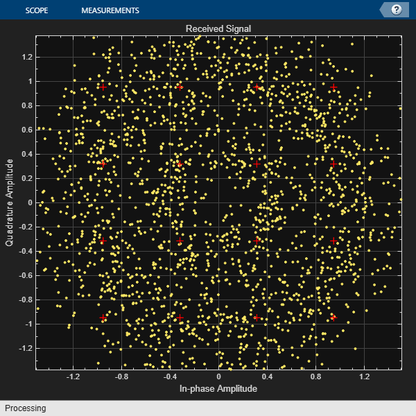
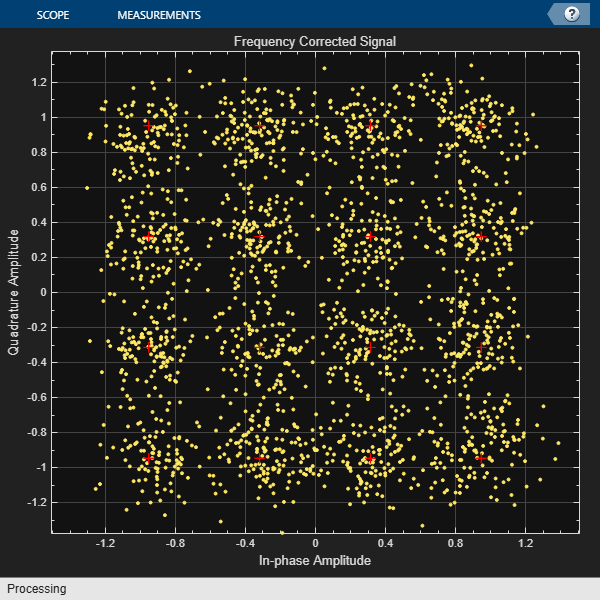
Plot the constellation diagrams of the received signal, frequency corrected signal, and frequency and timing synchronized signal. Specific constellation points cannot be identified in the received signal and can be only partially identified in the frequency corrected signal. However, the timing and frequency synchronized signal aligns with the expected QAM constellation points.
cdReceive(rxSig)
cdDoppler(rxCorr)
cdTiming(rxData)

See Also
You can also select a web site from the following list:
Americas
- América Latina (Español)
- Canada (English)
- United States (English)
Europe
- Belgium (English)
- Denmark (English)
- Deutschland (Deutsch)
- España (Español)
- Finland (English)
- France (Français)
- Ireland (English)
- Italia (Italiano)
- Luxembourg (English)
- Netherlands (English)
- Norway (English)
- Österreich (Deutsch)
- Portugal (English)
- Sweden (English)
- Switzerland
- United Kingdom (English)