DL-SCH and PDSCH Transmit and Receive Processing Chain
This example shows how to use 5G Toolbox™ features to model a 5G NR physical downlink shared channel (PDSCH) link, including all of the steps from transport block generation to bit decoding at the receiver end.
Introduction
This diagram shows the downlink shared channel (DL-SCH) and PDSCH transmit and receive processing chain.
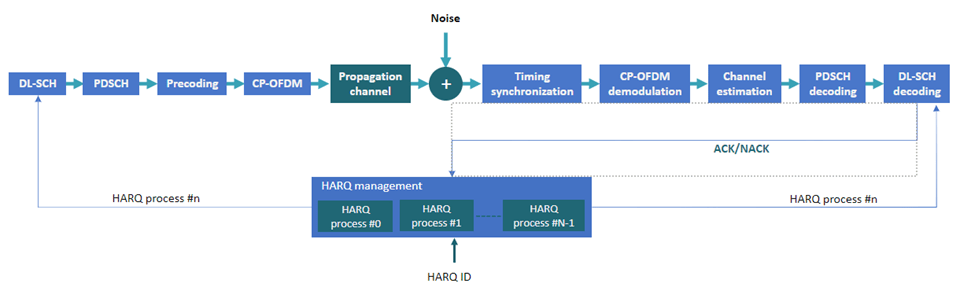
This example shows how to model these elements of a link-level simulation.
DL-SCH encoding
Hybrid ARQ (HARQ) management
PDSCH encoding
Multiple-input multiple-output (MIMO) precoding
OFDM modulation
Propagation channel and noise addition
Timing synchronization
OFDM demodulation
Channel estimation and equalization
PDSCH decoding
DL-SCH decoding
For an example of how to use link-level simulation to measure throughput, see NR PDSCH Throughput.
Simulation Parameters
Specify the signal-to-noise ratio (SNR), number of slots to simulate, and perfect channel estimation flag. To learn more about the SNR definition used in this example, see SNR Definition Used in Link Simulations.
SNRdB = 10;                % SNR in dB
totalNoSlots = 20;         % Number of slots to simulate
perfectEstimation = false; % Perfect synchronization and channel estimation
rng("default");            % Set default random number generator for repeatability
Carrier Configuration
Create a carrier configuration object. This object controls the numerology, such as, the subcarrier spacing, bandwidth, and cyclic prefix (CP) length. This example uses the default set of properties.
carrier = nrCarrierConfig
carrier =
  nrCarrierConfig with properties:

                NCellID: 1
      SubcarrierSpacing: 15
           CyclicPrefix: 'normal'
              NSizeGrid: 52
             NStartGrid: 0
                  NSlot: 0
                 NFrame: 0
    IntraCellGuardBands: [0×2 double]

   Read-only properties:
         SymbolsPerSlot: 14
       SlotsPerSubframe: 1
          SlotsPerFrame: 10
PDSCH and DM-RS Configuration
Create a PDSCH configuration object. Specify the modulation scheme (16-QAM) and the number of layers (2). Allocate all resource blocks (RBs) to the PDSCH (full band allocation). You can also specify other time-allocation parameters and demodulation reference signal (DM-RS) settings in this object.
pdsch = nrPDSCHConfig;
pdsch.Modulation = "16QAM";
pdsch.NumLayers = 2;
pdsch.PRBSet = 0:carrier.NSizeGrid-1;     % Full band allocation
Display the PDSCH parameters.
pdsch
pdsch =
  nrPDSCHConfig with properties:

                NSizeBWP: []
               NStartBWP: []
             ReservedPRB: {[1×1 nrPDSCHReservedConfig]}
              ReservedRE: []
              Modulation: '16QAM'
               NumLayers: 2
             MappingType: 'A'
        SymbolAllocation: [0 14]
                  PRBSet: [0 1 2 3 4 5 6 7 8 9 10 11 12 13 14 15 16 17 18 19 20 21 22 23 24 25 26 27 28 29 30 31 32 33 34 35 36 37 38 39 40 41 42 43 44 45 46 47 48 49 50 51]
              PRBSetType: 'VRB'
    VRBToPRBInterleaving: 0
           VRBBundleSize: 2
                     NID: []
                    RNTI: 1
                    DMRS: [1×1 nrPDSCHDMRSConfig]
              EnablePTRS: 0
                    PTRS: [1×1 nrPDSCHPTRSConfig]

   Read-only properties:
            NumCodewords: 1
Set the DM-RS parameters. To improve channel estimation, add an additional DM-RS position.
pdsch.DMRS.DMRSAdditionalPosition = 1;
Set the DM-RS configuration type and the DM-RS length, which determines the number of orthogonal DM-RS sequences or DM-RS ports.
DMRSConfigurationType = 1supports up to 4 DM-RS ports whenDMRSLength = 1.DMRSConfigurationType = 1supports up to 8 DM-RS ports whenDMRSLength = 2.DMRSConfigurationType = 2supports up to 6 DM-RS ports whenDMRSLength = 1. This is designed for multi-user MIMO (MU-MIMO).DMRSConfigurationType = 2supports up to 12 DM-RS ports whenDMRSLength = 2. This is designed for MU-MIMO.
The maximum number of layers must be less than or equal to the number of DM-RS ports.
pdsch.DMRS.DMRSConfigurationType = 1;
pdsch.DMRS.DMRSLength = 2;
pdsch.DMRS                            % Display DM-RS properties
ans =
nrPDSCHDMRSConfig with properties:
DMRSConfigurationType: 1
DMRSReferencePoint: 'CRB0'
DMRSTypeAPosition: 2
DMRSAdditionalPosition: 1
DMRSLength: 2
CustomSymbolSet: []
DMRSPortSet: []
NIDNSCID: []
NSCID: 0
NumCDMGroupsWithoutData: 2
DMRSDownlinkR16: 0
DMRSEnhancedR18: 0
Read-only properties:
CDMGroups: [0 0]
DeltaShifts: [0 0]
FrequencyWeights: [2×2 double]
TimeWeights: [2×2 double]
DMRSSubcarrierLocations: [6×2 double]
CDMLengths: [2 1]
DL-SCH Configuration
Specify the code rate, the number of HARQ processes, and the redundancy version (RV) sequence values. This sequence controls the RV retransmissions in case of error. To disable HARQ retransmissions, you can set rvSeq to a fixed value (for example, 0). For more information on how to model transport channels with HARQ, see Model 5G NR Transport Channels with HARQ.
NHARQProcesses = 16;     % Number of parallel HARQ processes
rvSeq = [0 2 3 1];
Take into account the number of codewords when specifying the coding rate. The number of codewords is a read-only property of the PDSCH configuration object that depends on the number of layers.
1 codeword for up to 4 layers
2 codewords for more than 4 layers
% Coding rate
if pdsch.NumCodewords == 1
    codeRate = 490/1024;
else
    codeRate = [490 490]./1024;
end
Create the DL-SCH encoder and decoder objects. To use multiple processes, set the MultipleHARQProcesses property to true for both objects. You do not need to specify the number of HARQ processes. The DL-SCH encoder and decoder objects can model up to 16 HARQ processes. To identify the active HARQ process when performing operations with the DL-SCH encoder and decoder objects, use the HARQprocessID property of the HARQ entity object, defined in the next section.
% Create DL-SCH encoder object
encodeDLSCH = nrDLSCH;
encodeDLSCH.MultipleHARQProcesses = true;
encodeDLSCH.TargetCodeRate = codeRate;

% Create DLSCH decoder object
decodeDLSCH = nrDLSCHDecoder;
decodeDLSCH.MultipleHARQProcesses = true;
decodeDLSCH.TargetCodeRate = codeRate;
decodeDLSCH.LDPCDecodingAlgorithm = "Normalized min-sum";
decodeDLSCH.MaximumLDPCIterationCount = 6;
HARQ Management
Create a HARQ entity object to manage the HARQ processes and the DL-SCH encoder and decoder buffers. For each HARQ process, a HARQ entity stores these elements:
HARQ ID number.
RV.
Transmission number, which indicates how many times a certain transport block has been transmitted.
Flag to indicate whether new data is required. New data is required when a transport block is received successfully or if a sequence timeout has occurred (all RV transmissions have failed).
Flag to indicate whether a sequence timeout has occurred (all RV transmissions have failed).
harqEntity = HARQEntity(0:NHARQProcesses-1,rvSeq,pdsch.NumCodewords);
Channel Configuration
Specify the number of transmit and receive antennas.
nTxAnts = 8;
nRxAnts = 8;

% Check that the number of layers is valid for the number of antennas
if pdsch.NumLayers > min(nTxAnts,nRxAnts)
    error("The number of layers ("+string(pdsch.NumLayers)+") must be smaller than min(nTxAnts,nRxAnts) ("+string(min(nTxAnts,nRxAnts))+")")
end
Create a channel object.
channel = nrTDLChannel;
channel.DelayProfile = "TDL-C";
channel.NumTransmitAntennas = nTxAnts;
channel.NumReceiveAntennas = nRxAnts;
Set the channel sample rate to that of the OFDM signal. To obtain the sampling rate of the OFDM signal, use the nrOFDMInfo function.
ofdmInfo = nrOFDMInfo(carrier);
channel.SampleRate = ofdmInfo.SampleRate;
Set the channel output type so that perfect channel estimation and timing estimation can be calculated at the same time when filtering the signal.
channel.ChannelResponseOutput = 'ofdm-response';Transmission and Reception
Set up a loop to simulate the transmission and reception of slots. Create a comm.ConstellationDiagram to display the constellation of the equalized signal.
constPlot = comm.ConstellationDiagram;                                          % Constellation diagram object
constPlot.ReferenceConstellation = getConstellationRefPoints(pdsch.Modulation); % Reference constellation values
constPlot.EnableMeasurements = 1;                                               % Enable EVM measurements

% Initial timing offset
offset = 0;

estChannelGrid = getInitialChannelEstimate(channel,carrier);
newPrecodingWeight = getPrecodingMatrix(pdsch.PRBSet,pdsch.NumLayers,estChannelGrid);

for nSlot = 0:totalNoSlots-1
    % New slot
    carrier.NSlot = nSlot;
Calculate Transport Block Size
The transport block size is the number of bits to send to the channel coding stages. This value depends on the capacity of the PDSCH. To calculate the transport block size, use the nrTBS function.
    % Generate PDSCH indices info, which is needed to calculate the transport
    % block size
    [pdschIndices,pdschInfo] = nrPDSCHIndices(carrier,pdsch);

    % Calculate transport block sizes
    Xoh_PDSCH = 0;
    trBlkSizes = nrTBS(pdsch.Modulation,pdsch.NumLayers,numel(pdsch.PRBSet),pdschInfo.NREPerPRB,codeRate,Xoh_PDSCH);
HARQ Processing (Buffer Management)
This section explains the buffer management in the encoder and decoder.
DL-SCH encoder buffers: Generate a new transport block if new data is required for the active HARQ process. Store the transport block in the corresponding buffer. If new data is not required, the DL-SCH encoder uses its buffered bits for retransmission.
DL-SCH decoder buffers: The soft buffers in the receiver store previously received versions of the same codeword. These buffers are cleared automatically upon successful reception (no CRC error). However, if the RV sequence ends without successful decoding, flush the buffers manually by using the
resetSoftBufferobject function.
    % Get new transport blocks and flush decoder soft buffer, as required
    for cwIdx = 1:pdsch.NumCodewords
        if harqEntity.NewData(cwIdx)
            % Create and store a new transport block for transmission
            trBlk = randi([0 1],trBlkSizes(cwIdx),1);
            setTransportBlock(encodeDLSCH,trBlk,cwIdx-1,harqEntity.HARQProcessID);

            % If the previous RV sequence ends without successful
            % decoding, flush the soft buffer
            if harqEntity.SequenceTimeout(cwIdx)
                resetSoftBuffer(decodeDLSCH,cwIdx-1,harqEntity.HARQProcessID);
            end
        end
    end
DL-SCH Encoding
Encode the transport blocks. The transport block is already stored in one of the internal soft buffers of the DL-SCH encoder object.
codedTrBlock = encodeDLSCH(pdsch.Modulation,pdsch.NumLayers,pdschInfo.G,harqEntity.RedundancyVersion,harqEntity.HARQProcessID);
PDSCH Modulation and MIMO Precoding
Generate PDSCH symbols from the coded transport blocks.
pdschSymbols = nrPDSCH(carrier,pdsch,codedTrBlock);
Get the precoding weights. This example assumes channel knowledge for precoding. (For an example of how to use the channel estimate at the receiver to calculate the weights used for the transmission in the next slot, see NR PDSCH Throughput.)
precodingWeights = newPrecodingWeight;
Precode the PDSCH symbols.
pdschSymbolsPrecoded = pdschSymbols*precodingWeights;
PDSCH DM-RS Generation
Generate DM-RS symbols and indices.
    dmrsSymbols = nrPDSCHDMRS(carrier,pdsch);
    dmrsIndices = nrPDSCHDMRSIndices(carrier,pdsch);
Mapping to Resource Grid
Generate an empty resource grid. This grid represents a slot.
pdschGrid = nrResourceGrid(carrier,nTxAnts);
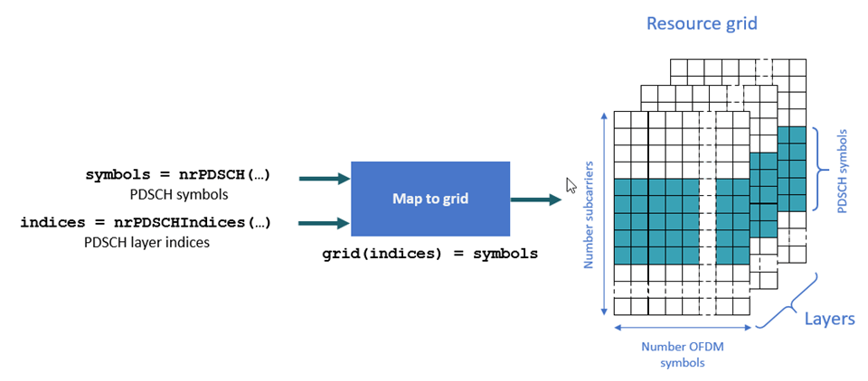
The nrPDSCHIndices function generates indices that refer to layers and not antennas. This format is useful when mapping PDSCH symbols directly to layers. In this case, the resulting resource grids are not precoded. This figure shows the mapping process of the PDSCH symbols to as many resource grids as layers.
Because this example applies MIMO precoding to the PDSCH symbols before mapping them to the resource grids, the MIMO-precoded PDSCH symbols refer to antennas and not layers. To convert layer indices to antenna indices, use the nrExtractResources function. This figure shows the mapping process of MIMO-precoded symbols to as many resource grids as transmit antennas.
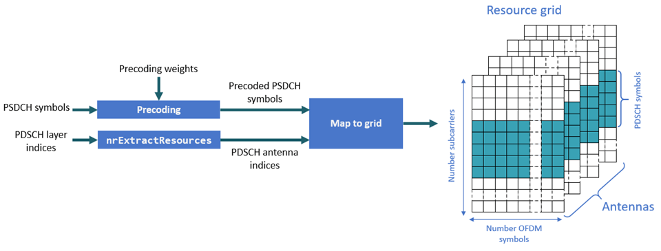
    [~,pdschAntIndices] = nrExtractResources(pdschIndices,pdschGrid);
    pdschGrid(pdschAntIndices) = pdschSymbolsPrecoded;
MIMO-precode and map the DM-RS symbols to the resource grid. Similar to the PDSCH indices, the DM-RS indices refer to layers. To convert these layer indices to antenna indices, use the nrExtractResources function again.
    % PDSCH DM-RS precoding and mapping
    for p = 1:size(dmrsSymbols,2)
        [~,dmrsAntIndices] = nrExtractResources(dmrsIndices(:,p),pdschGrid);
        pdschGrid(dmrsAntIndices) = pdschGrid(dmrsAntIndices) + dmrsSymbols(:,p)*precodingWeights(p,:);
    end
OFDM Modulation
OFDM-modulate the resource grid.
[txWaveform,waveformInfo] = nrOFDMModulate(carrier,pdschGrid);
Propagation Channel
The propagation channel generates N output samples for an input with N samples. However, the block of N output samples includes the channel filter transient (K samples). Because the synchronization stage removes this initial transient, if a slot at the channel output has N samples, N-K samples remain after synchronization. N-K samples are not enough to decode a slot-worth of data. Part of the slot samples are in the channel filter delay line and are not flushed yet. To flush all relevant samples out of the channel filter, pad the input signal with zeros. The maximum delay that the channel filter introduces affects the size of the padding. The padding accounts for the delay introduced by all multipath components and the channel filter implementation delay. This figure shows the need for zero padding before a waveform enters the channel.

Pad the input signal with enough zeros to ensure that the generated signal is flushed out of the channel filter.
    chInfo = info(channel);
    maxChDelay = chInfo.MaximumChannelDelay;
    txWaveform = [txWaveform; zeros(maxChDelay,size(txWaveform,2))];
Send the signal through the channel and add noise. The output OFDM channel response ofdmChannelResponse and timing offset timingOffset are only applicable if perfect channel estimation is enabled.
    [rxWaveform,ofdmChannelResponse,timingOffset] = channel(txWaveform,carrier);
    [noise,nVar] = generateAWGN(SNRdB,nRxAnts,waveformInfo.Nfft,size(rxWaveform));
    rxWaveform = rxWaveform + noise;
Timing Synchronization
You can perform perfect or practical synchronization.
Perfect synchronization assumes channel knowledge. The channel returns this information directly when the channel response output type is set to
'ofdm-response'.Practical synchronization performs a cross-correlation of the received signal with the PDSCH DM-RS symbols in the time domain (
nrTimingEstimate). In some adverse cases, this cross-correlation can be weak due to fading or noise, resulting in an erroneous timing offset. The functionhSkipWeakTimingOffsetchecks the magnitude of the cross-correlationmag. If the cross-correlation is weak, the function ignores the current timing estimate and instead uses the previous estimate (offset).
Perform perfect or practical timing estimation and synchronization.
    if perfectEstimation
        % Perfect timing estimation is provided by the channel
        offset = timingOffset;
    else
        [t,mag] = nrTimingEstimate(carrier,rxWaveform,dmrsIndices,dmrsSymbols);
        offset = hSkipWeakTimingOffset(offset,t,mag);
    end
    rxWaveform = rxWaveform(1+offset:end,:);
OFDM Demodulation
OFDM-demodulate the synchronized signal.
rxGrid = nrOFDMDemodulate(carrier,rxWaveform);
Channel Estimation
Channel estimation provides a representation of the channel effects per resource element (RE). The equalizer uses this information to compensate for the distortion introduced by the channel.
You can perform perfect or practical channel estimation.
Perfect channel estimation assumes channel knowledge. The channel returns this information directly when the channel response output type is set to
'ofdm-response'.Practical channel estimation uses the PDSCH DM-RS to estimate the channel conditions and uses noise averaging and interpolation to obtain an estimate for all REs in the slot. Because the DM-RSs are specified per layer, the resulting practical channel estimate represents the channel conditions between the transmit layers and the receive antennas. The practical channel estimate includes the effect of the MIMO precoding operation.
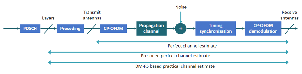
This figure shows the reference points of the channel estimates in the downlink processing chain.
Perform perfect or practical channel estimation.
    if perfectEstimation
        % Perfect channel estimation between transmit and receive antennas
        % provided by the channel
        estChGridAnts = ofdmChannelResponse;

        % Use the precalculated noise variance as the perfect noise
        % estimate
        noiseEst = nVar;

        % Get precoding matrix for next slot
        newPrecodingWeight = getPrecodingMatrix(pdsch.PRBSet,pdsch.NumLayers,estChGridAnts);

        % Apply precoding to estChGridAnts. The resulting estimate is for
        % the channel estimate between layers and receive antennas.
        estChGridLayers = precodeChannelEstimate(estChGridAnts,precodingWeights.');
    else
        % Perform practical channel estimation between layers and receive
        % antennas.
        [estChGridLayers,noiseEst] = nrChannelEstimate(carrier,rxGrid,dmrsIndices,dmrsSymbols,'CDMLengths',pdsch.DMRS.CDMLengths);

        % Remove precoding from estChannelGrid before precoding
        % matrix calculation
        estChGridAnts = precodeChannelEstimate(estChGridLayers,conj(precodingWeights));

        % Get precoding matrix for next slot
        newPrecodingWeight = getPrecodingMatrix(pdsch.PRBSet,pdsch.NumLayers,estChGridAnts);
    end
Plot the channel estimate between the first layer and the first receive antenna.
    mesh(abs(estChGridLayers(:,:,1,1)));
    title('Channel Estimate');
    xlabel('OFDM Symbol');
    ylabel("Subcarrier");
    zlabel("Magnitude");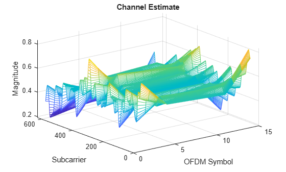
At this point, you can use the channel estimate to obtain the precoding matrix for transmission in the next slot. Because this example assumes channel knowledge at the transmitter, you do not need to calculate the precoding matrix at the receiver end. For an example of how to calculate the precoding matrix for data transmission based on a channel estimate at the receiver, see NR PDSCH Throughput.
Equalization
The equalizer uses the channel estimate to compensate for the distortion introduced by the channel.
Extract the PDSCH symbols from the received grid and associated channel estimates. The csi output has channel state information (CSI) for each of the equalized PDSCH symbols. The CSI is a measure of the channel conditions for each PDSCH symbol. Use the CSI to weight the decoded soft bits after PDSCH decoding, effectively increasing the importance of symbols experiencing better channel conditions.
    [pdschRx,pdschHest] = nrExtractResources(pdschIndices,rxGrid,estChGridLayers);
    [pdschEq,csi] = nrEqualizeMMSE(pdschRx,pdschHest,noiseEst);
Plot the constellation of the equalized symbols. The plot includes the constellation diagrams for all layers.
    constPlot.ChannelNames = "Layer "+(pdsch.NumLayers:-1:1);
    constPlot.ShowLegend = true;
    % Constellation for the first layer has a higher SNR than that for the
    % last layer. Flip the layers so that the constellations do not mask
    % each other.
    constPlot(fliplr(pdschEq));
![]()
PDSCH Decoding
Decode the equalized PDSCH symbols and obtain the soft bit codewords.
[dlschLLRs,rxSymbols] = nrPDSCHDecode(carrier,pdsch,pdschEq,noiseEst);
Scale the soft bits or log-likelihood ratios (LLRs) by the CSI. This scaling applies a larger weight to the symbols in the REs with better channel conditions.
    % Scale LLRs by CSI
    csi = nrLayerDemap(csi);                                    % CSI layer demapping
    for cwIdx = 1:pdsch.NumCodewords
        Qm = length(dlschLLRs{cwIdx})/length(rxSymbols{cwIdx}); % Bits per symbol
        csi{cwIdx} = repmat(csi{cwIdx}.',Qm,1);                 % Expand by each bit per symbol
        dlschLLRs{cwIdx} = dlschLLRs{cwIdx} .* csi{cwIdx}(:);   % Scale
    end
DL-SCH Decoding
Decode the LLRs and check for errors.
    decodeDLSCH.TransportBlockLength = trBlkSizes;
    [decbits,blkerr] = decodeDLSCH(dlschLLRs,pdsch.Modulation,pdsch.NumLayers, ...
        harqEntity.RedundancyVersion,harqEntity.HARQProcessID);
HARQ Process Update
Update the current HARQ process with the resulting block error status, and then advance to the next process. This step updates the information related to the active HARQ process in the HARQ entity.
statusReport = updateAndAdvance(harqEntity,blkerr,trBlkSizes,pdschInfo.G);
Summarize HARQ and decoding information for the present slot.
    disp("Slot "+(nSlot)+". "+statusReport);
end % for nSlot = 0:totalNoSlots
Slot 0. HARQ Proc 0: CW0: Initial transmission passed  (TBS=24072,RV=0,CR=0.482212).
Slot 1. HARQ Proc 1: CW0: Initial transmission passed  (TBS=24072,RV=0,CR=0.482212).
Slot 2. HARQ Proc 2: CW0: Initial transmission passed  (TBS=24072,RV=0,CR=0.482212).
Slot 3. HARQ Proc 3: CW0: Initial transmission passed  (TBS=24072,RV=0,CR=0.482212).
Slot 4. HARQ Proc 4: CW0: Initial transmission passed  (TBS=24072,RV=0,CR=0.482212).
Slot 5. HARQ Proc 5: CW0: Initial transmission passed  (TBS=24072,RV=0,CR=0.482212).
Slot 6. HARQ Proc 6: CW0: Initial transmission passed  (TBS=24072,RV=0,CR=0.482212).
Slot 7. HARQ Proc 7: CW0: Initial transmission passed  (TBS=24072,RV=0,CR=0.482212).
Slot 8. HARQ Proc 8: CW0: Initial transmission passed  (TBS=24072,RV=0,CR=0.482212).
Slot 9. HARQ Proc 9: CW0: Initial transmission passed  (TBS=24072,RV=0,CR=0.482212).
Slot 10. HARQ Proc 10: CW0: Initial transmission passed  (TBS=24072,RV=0,CR=0.482212).
Slot 11. HARQ Proc 11: CW0: Initial transmission passed  (TBS=24072,RV=0,CR=0.482212).
Slot 12. HARQ Proc 12: CW0: Initial transmission passed  (TBS=24072,RV=0,CR=0.482212).
Slot 13. HARQ Proc 13: CW0: Initial transmission passed  (TBS=24072,RV=0,CR=0.482212).
Slot 14. HARQ Proc 14: CW0: Initial transmission passed  (TBS=24072,RV=0,CR=0.482212).
Slot 15. HARQ Proc 15: CW0: Initial transmission passed  (TBS=24072,RV=0,CR=0.482212).
Slot 16. HARQ Proc 0: CW0: Initial transmission passed  (TBS=24072,RV=0,CR=0.482212).
Slot 17. HARQ Proc 1: CW0: Initial transmission passed  (TBS=24072,RV=0,CR=0.482212).
Slot 18. HARQ Proc 2: CW0: Initial transmission passed  (TBS=24072,RV=0,CR=0.482212).
Slot 19. HARQ Proc 3: CW0: Initial transmission passed  (TBS=24072,RV=0,CR=0.482212).
Local Functions
function [noise,nVar] = generateAWGN(SNRdB,nRxAnts,Nfft,sizeRxWaveform)
% Generate AWGN for a given value of SNR in dB (SNRDB), which is the
% receiver SNR per RE and antenna, assuming the channel does
% not affect the power of the signal. NRXANTS is the number of receive
% antennas. NFFT is the FFT size used in OFDM demodulation. SIZERXWAVEFORM
% is the size of the receive waveform used to calculate the size of the
% noise matrix.

    % Normalize noise power by the IFFT size used in OFDM modulation, as
    % the OFDM modulator applies this normalization to the transmitted
    % waveform. Also normalize by the number of receive antennas, as the
    % channel model applies this normalization to the received waveform by
    % default. The SNR is defined per RE for each receive antenna (TS
    % 38.101-4).
    SNR = 10^(SNRdB/10); % Calculate linear noise gain
    N0 = 1/sqrt(nRxAnts*double(Nfft)*SNR);
    noise = N0*randn(sizeRxWaveform,"like",1i);
    nVar = N0^2*double(Nfft);
end

function wtx = getPrecodingMatrix(PRBSet,NLayers,hestGrid)
% Calculate precoding matrix given an allocation and a channel estimate

    % Allocated subcarrier indices
    allocSc = (1:12)' + 12*PRBSet(:).';
    allocSc = allocSc(:);

    % Average channel estimate
    [~,~,R,P] = size(hestGrid);
    estAllocGrid = hestGrid(allocSc,:,:,:);
    Hest = permute(mean(reshape(estAllocGrid,[],R,P)),[2 3 1]);

    % SVD decomposition
    [~,~,V] = svd(Hest);

    wtx = V(:,1:NLayers).';
    wtx = wtx/sqrt(NLayers); % Normalize by NLayers
end

function estChannelGrid = getInitialChannelEstimate(channel,carrier)
% Obtain an initial channel estimate for calculating the precoding matrix.
% This function assumes a perfect channel estimate

    % Clone of the channel
    chClone = channel.clone();
    chClone.release();

    % No filtering needed to get channel path gains
    chClone.ChannelFiltering = false;

    % Set channel response output type to calculate perfect channel
    % estimation
    chClone.ChannelResponseOutput = 'ofdm-response';

    % Get perfect channel estimate directly from the channel
    estChannelGrid = chClone(carrier);
end

function refPoints = getConstellationRefPoints(mod)
% Calculate the reference constellation points for a given modulation
% scheme.
    switch mod
        case "QPSK"
            nPts = 4;
        case "16QAM"
            nPts = 16;
        case "64QAM"
            nPts = 64;
        case "256QAM"
            nPts = 256;
    end
    binaryValues = int2bit(0:nPts-1,log2(nPts));
    refPoints = nrSymbolModulate(binaryValues(:),mod);
end

function estChannelGrid = precodeChannelEstimate(estChannelGrid,W)
% Apply precoding matrix W to the last dimension of the channel estimate.

    % Linearize 4-D matrix and reshape after multiplication
    K = size(estChannelGrid,1);
    L = size(estChannelGrid,2);
    R = size(estChannelGrid,3);
    estChannelGrid = reshape(estChannelGrid,K*L*R,[]);
    estChannelGrid = estChannelGrid*W;
    estChannelGrid = reshape(estChannelGrid,K,L,R,[]);

end