Configure AUTOSAR Port Parameters for Communication with Parameter Software Component
The AUTOSAR standard defines port-based parameters for parameter communication. AUTOSAR
parameter communication relies on a parameter software component
(ParameterSwComponent) and one or more atomic software components
that require port-based access to parameter data. The
ParameterSwComponent represents memory containing AUTOSAR parameters
and provides parameter data to connected atomic software components. For information about
port-based parameter workflows, see Port Parameters.
Configure AUTOSAR Software Components for Parameter Communication
In Simulink®, you can model the receiver side of AUTOSAR port-based parameter communication. To configure an AUTOSAR atomic software component as a parameter receiver:
In an AUTOSAR component model, in the AUTOSAR Dictionary, create an AUTOSAR parameter interface, parameter data elements, and a parameter receiver port.
In the Simulink model workspace, create a parameter, mark it as an argument, and set an initial value. You can use Simulink parameter, lookup table, and breakpoint objects.
Map the Simulink model workspace parameter or lookup table to an AUTOSAR parameter receiver port and parameter interface data element. Use the Parameters tab of the Code Mappings editor or the
mapParameterfunction.
This example shows how to configure an AUTOSAR software component as a receiver for parameter communication.
Open a model configured for AUTOSAR code generation in which the software component requires port-based access to parameter data.
Open the AUTOSAR Dictionary. To add a parameter interface to the model, select the Parameter Interfaces view and click the Add button
 . In the Add Interfaces dialog box, specify
the name of the new interface and set Number of Data
Elements to
. In the Add Interfaces dialog box, specify
the name of the new interface and set Number of Data
Elements to 1. Click Add.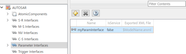
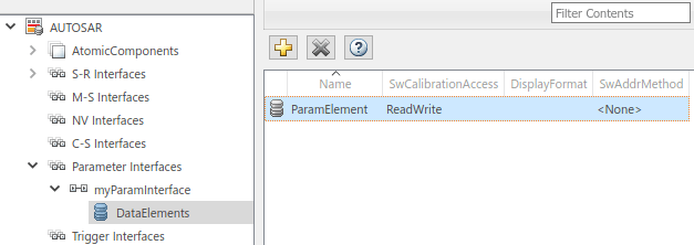
Expand Parameter Interfaces and select the DataElements view. Examine and modify the properties of the associated data element that you created, including its name.
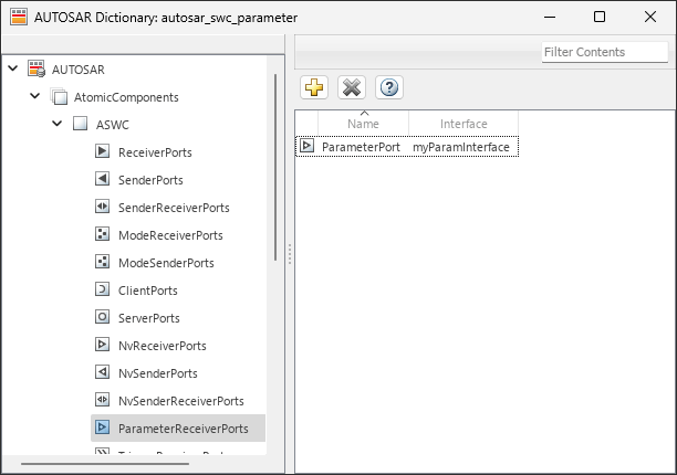
Expand AtomicComponents and expand the component. To add a parameter receiver port to the model, go to the ParameterReceiverPorts view and click the Add button
. In the Add Ports dialog box, specify the
name of the new port and set Interface to the name of the
parameter interface that you created. Click Add.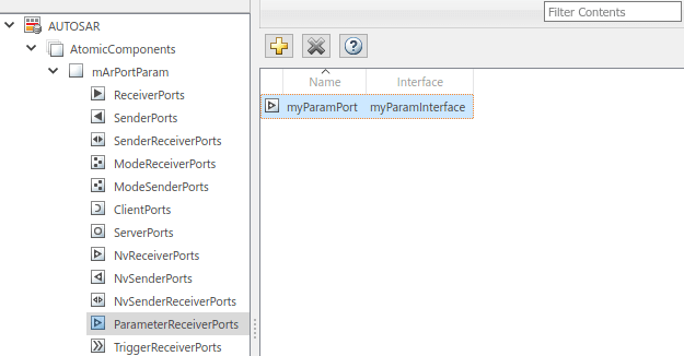
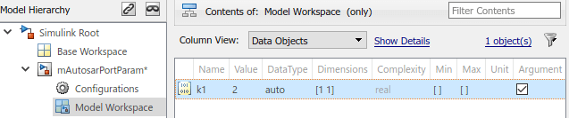
In the Simulink model workspace, create a data object for the parameter. For example, use Model Explorer. With the data object selected, set the Name and Value fields. To configure the parameter as a model argument (that is, unique to each instance of a multi-instance model), select the Argument check box.
Reference the data object name in the model. For example, enter
k1in the Gain parameter field of a Gain block.Open the Code Mappings editor and select the Parameters tab. In the Model Parameter Arguments group, select the parameter data object that you created. In the Mapped To menu, select AUTOSAR parameter type
PortParameter.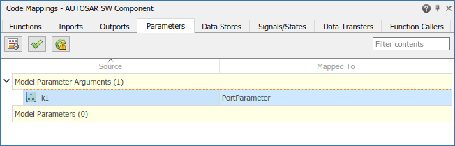
To view and modify other code and calibration attributes for the parameter, click the Edit icon
 .
.Set Port to the name of the parameter receiver port that you configured in the AUTOSAR Dictionary.
Set DataElement to the name of the parameter interface data element that you configured in the AUTOSAR Dictionary.
For more information, see Map Model Workspace Parameters to AUTOSAR Component Parameters.
When you generate code for the AUTOSAR component model:
The exported ARXML files contain descriptions of the parameter receiver component, parameter interface, parameter data element, and parameter receiver port.
<PARAMETER-INTERFACE UUID="...">
    <SHORT-NAME>myParamInterface</SHORT-NAME>
    <IS-SERVICE>false</IS-SERVICE>
    <PARAMETERS>
        <PARAMETER-DATA-PROTOTYPE UUID="...">
            <SHORT-NAME>ParamElement</SHORT-NAME>
        ...
        </PARAMETER-DATA-PROTOTYPE>
    </PARAMETERS>
</PARAMETER-INTERFACE>
The generated C code contains AUTOSAR port parameter
Rtefunction calls./* Model step function */ void mArPortParam_Step(void) { ... Rte_IWrite_mArPortParam_Step_Out2_Out2(Rte_Prm_myParamPort_ParamElement() * Rte_IRead_mArPortParam_Step_In2_In2()); }
At run time, the software can access the parameter data element as a port-based parameter.
Create Parameter Provider Ports Using ParameterSender Ports in AUTOSAR Software Architecture
This example shows how to reference a component model in an AUTOSAR architecture (requires System Composer™), add a parameter software component, and generate code containing descriptions of the parameter software component, interface, connectors, and ports.
Create an AUTOSAR architecture model, and load example model autosar_swc_parameter.
archModel = autosar.arch.createModel("AUTOSARArchitecture");
load_system("autosar_swc_parameter");
Add a component to the architecture model by using the addComponent function.
component = addComponent(archModel,"SensorComponent", ...
    Kind="SensorActuator");
Link the component model autosar_swc_parameter to the component in the architecture by using the linkToModel function.
linkToModel(component,"autosar_swc_parameter");Add ports to the architecture model canvas by using the addPort function. Connect the architecture to the component by using the connect function.
addPort(archModel,"Sender","SenderPort");
addPort(archModel,"Receiver","ReceivePort");
connect(archModel,archModel.Ports(1),component.Ports(1));
connect(archModel,archModel.Ports(2),component.Ports(2));
Add a parameter software component of type ParameterSender to the architecture model.
parameterComponent = addComponent(archModel,"ParameterProvider",...
    Kind="ParameterComponent")
parameterComponent =
  ParameterComponent with properties:

      Name: 'ParameterProvider'
    Parent: [1×1 autosar.arch.Model]
     Ports: [0×0 autosar.arch.ParameterPort]
Add a parameter sender port to the parameter component. This port must be named ParameterPort to match the name of the ParameterReceiverPort already present in autosar_swc_parameter.
paramPort = addPort(parameterComponent,"ParameterSender",...
    "ParameterPort")
paramPort =
  ParameterPort with properties:

      Name: 'ParameterPort'
    Parent: [1×1 autosar.arch.ParameterComponent]
Export ARXML by using the export function.
evalc("export(archModel)")ans =
'Building component: autosar_swc_parameter (1 out of 1)
### Searching for referenced models in model 'autosar_swc_parameter'.
### Total of 1 models to build.
### Starting build procedure for: autosar_swc_parameter
### Generating XML files description for: autosar_swc_parameter
### Successful completion of code generation for: autosar_swc_parameter
Build Summary
Top model targets:
Model Build Reason Status Build Duration
===========================================================================================================
autosar_swc_parameter Information cache folder or artifacts were missing. Code generated. 0h 0m 19.593s
1 of 1 models built (0 models already up to date)
Build duration: 0h 0m 21.165s
Exporting composition: AUTOSARArchitecture
### Generating XML description files for: AUTOSARArchitecture
### Successful completion of export for: AUTOSARArchitecture
### Creating HTML report Architecture Export Report
'
Inspect the ARXML files. The parameter software component descriptions are in the AUTOSARArchitecture_component.arxml file.
<SHORT-NAME>Components</SHORT-NAME>
<ELEMENTS>
    <PARAMETER-SW-COMPONENT-TYPE UUID="...">
        <SHORT-NAME>ParameterProvider</SHORT-NAME>
        <PORTS>
            <P-PORT-PROTOTYPE UUID="...">
                <SHORT-NAME>ParameterPort</SHORT-NAME>
                <PROVIDED-COM-SPECS>
                    <PARAMETER-PROVIDE-COM-SPEC>
                        <INIT-VALUE>
                            <NUMERICAL-VALUE-SPECIFICATION>
                                <SHORT-LABEL>DefaultInitValue_float64_5</SHORT-LABEL>
                                <VALUE>5</VALUE>
                            </NUMERICAL-VALUE-SPECIFICATION>
                        </INIT-VALUE>
                        <PARAMETER-REF DEST="PARAMETER-DATA-PROTOTYPE">/Company/Powertrain/Interfaces/myParamInterface/ParamElement</PARAMETER-REF>
                    </PARAMETER-PROVIDE-COM-SPEC>
                </PROVIDED-COM-SPECS>
            </P-PORT-PROTOTYPE>
        </PORTS>
    </PARAMETER-SW-COMPONENT-TYPE>
</ELEMENTS>
The AUTOSARArchitecture_composition.arxml file contains connector descriptions. The parameter software components are connected to ports of the same name.
<CONNECTORS>
    <ASSEMBLY-SW-CONNECTOR UUID="...">
        <SHORT-NAME>ParameterProvider_ParameterPort_SensorComponent_ParameterPort</SHORT-NAME>
        <PROVIDER-IREF>
            <CONTEXT-COMPONENT-REF DEST="SW-COMPONENT-PROTOTYPE">/Components/AUTOSARArchitecture/ParameterProvider</CONTEXT-COMPONENT-REF>
            <TARGET-P-PORT-REF DEST="P-PORT-PROTOTYPE">/Components/ParameterProvider/ParameterPort</TARGET-P-PORT-REF>
        </PROVIDER-IREF>
        <REQUESTER-IREF>
            <CONTEXT-COMPONENT-REF DEST="SW-COMPONENT-PROTOTYPE">/Components/AUTOSARArchitecture/SensorComponent</CONTEXT-COMPONENT-REF>
            <TARGET-R-PORT-REF DEST="R-PORT-PROTOTYPE">/Components/ASWC/ParameterPort</TARGET-R-PORT-REF>
        </REQUESTER-IREF>
    </ASSEMBLY-SW-CONNECTOR>
See Also
Functions
getParameter|mapParameter|addComponent|addPort|find|export