Audio Out
Send processed audio samples to audio devices
Add-On Required: This feature requires the Embedded Coder Support Package for STMicroelectronics STM32 Processors add-on.
Libraries:
Embedded Coder Support Package for STMicroelectronics STM32 Processors /
STM32F4-Discovery
Description
This block writes the processed audio data to the audio device connected to the processor on the STM32F4–Discovery™ board. You can send audio samples at different rates such as 16kHz, 32kHz etc. with different frame sizes.
You can play mono ([1xN] or [Nx1] ) or stereo [Nx2] audio frames on this block.
In the Configuration Parameters dialog, under Coder Target,
you can select “Audio Out” block DMA interrupt as
the Scheduler Interrupt Source. This ensures
that the processing algorithm is synchronized with the Audio out block
interrupt.
When you select this option, make sure to schedule the Audio out block at the base rate.
Note
You cannot play [1x1] audio samples on this block as the frame requires at least two samples.
Send Processed Audio Samples Using Double Buffering
The Audio Out block uses a double buffering mechanism to send data to the audio device.
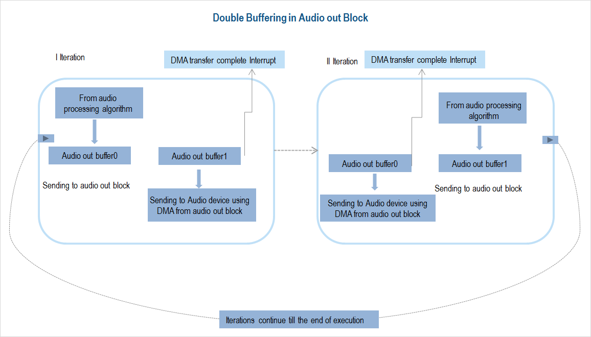
With double buffering, one buffer is used by the DMA to transfer audio frame from the processor to the audio device while the other buffer is used to receive the processed audio frame from your audio algorithm. Doing so helps to prevent overwriting the buffer while sending the data to the audio device.
When you send an audio frame of length N samples,
the block creates two buffers of length N samples.
The following describes the double buffering mechanism in the Audio Out block.
In the first iteration, when the processed audio signal is sent to the audio device from ‘Audio out buffer1’, the ‘Audio out buffer0’ is filled with audio signal from the audio processing algorithm.
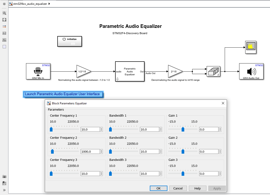
In the first iteration, the ‘Audio out buffer1’ does not contain the audio samples. Therefore, the audio samples from the Audio Out block are delayed by one audio frame. If your model has Mic In and the Audio Out blocks, then there is a time delay of two audio frames as the Mic In block also uses the same double buffering technique.
After the DMA completes sending out the processed data from ‘Audio out buffer1’, an interrupt is generated.
In the second iteration, when the processed audio signal is sent out to the audio device from Audio out buffer0, the ‘Audio out buffer1’ is filled with the audio data from the audio processing algorithm.

Examples
Ports
Input
Parameters
Extended Capabilities
Version History
Introduced in R2013b

