Generate Reusable Code from Stateflow Atomic Subcharts
Generate Reusable Code for Linked Atomic Subcharts
To specify code generation parameters for linked atomic subcharts from the same library:
Open the library model that contains your atomic subchart.
Unlock the library.
Right-click the library chart and select Block Parameters.
In the dialog box, specify the following parameters:
On the Main tab, select parameter Treat as atomic unit.
On the Code Generation tab, set parameter Function packaging to
Reusable function.Set File name options to
User specified.For File name, enter the name of the file without an extension.
Click OK to apply the changes.
(OPTIONAL) Customize the generated function names for atomic subcharts:
Set model configuration parameter System target file to
ert.tlc.For model configuration parameter Subsystem methods, specify the format of the function names using a combination of the following naming rule tokens:
$R— root model name$F— type of interface function for the atomic subchart$N— block name$H— subsystem index$M— name-mangling text
Click OK to apply the changes.
When you generate code for your model, a separate file stores the code for linked atomic subcharts from the same library.
Generate Reusable Code for Unlinked Atomic Subcharts
To specify code generation parameters for an unlinked atomic subchart:
In your chart, right-click the atomic subchart and select Properties.
In the dialog box, specify the following properties:
Set property Code generation function packaging to
Reusable function.Set Code generation file name options to
User specified.For Code generation file name, enter the name of the file without extension.
Click OK to apply the changes.
(OPTIONAL) Customize the generated function names for atomic subcharts:
Set model configuration parameter System target file to
ert.tlc.For model configuration parameter Subsystem methods, specify the format of the function names using a combination of the following naming rule tokens:
$R— root model name$F— type of interface function for the atomic subchart$N— block name$H— subsystem index$M— name-mangling text
Click OK to apply the changes.
When you generate code for your model, a separate file stores the code for the atomic subchart. For more information, see Generate Code from Atomic Subcharts.
Generate Reusable Code for Unit Testing
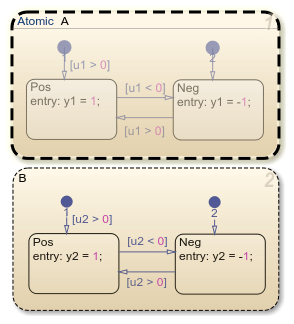
Convert a State to an Atomic Subchart
To convert state A to an atomic subchart, right-click the state and select Group & Subchart > Atomic Subchart. State A changes to an atomic subchart:
Set Up a Standalone C File for the Atomic Subchart
Open the properties dialog box for A.
Set property Code generation function packaging to
Reusable function.Set Code generation file name options to
User specified.For Code generation file name, enter
saturatoras the name of the file.Click OK.
Set Up the Code Generation Report
Set model configuration parameter System target file to
ert.tlc.Select model configuration parameters Create code generation report and Open report automatically.
Select parameters Code-to-model and Model-to-code.
Click Apply.
Customize the Generated Function Names
Set model configuration parameter Subsystem methods to the format scheme
$R$N$M$F, where:$Ris the root model name.$Nis the block name.$Mis the mangle token.$Fis the type of interface function for the atomic subchart.
For more information, see Subsystem methods.
Click Apply.
Generate Code for Only the Atomic Subchart
To generate code for your model, press Ctrl+B. In the code generation report that appears, you see a separate file that contains the generated code for the atomic subchart.
To inspect the code for saturator.c, click the hyperlink in the
report to see the following code:
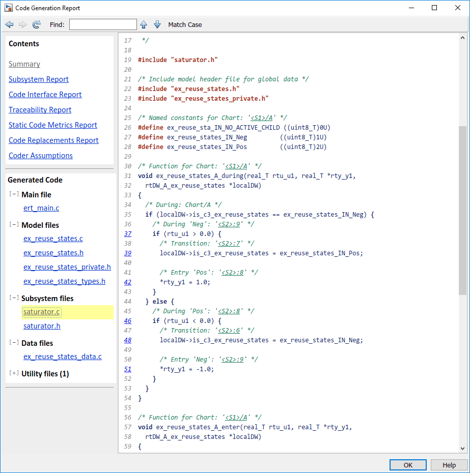
Line 28 shows that the during function generated for the atomic
subchart has the name ex_reuse_states_A_during. This name follows
the format scheme $R$N$M$F specified for Subsystem
methods:
$Ris the root model name,ex_reuse_states.$Nis the block name,A.$Mis the mangle token, which is empty.$Fis the type of interface function for the atomic subchart,during.
Note
The line numbers shown can differ from the numbers that appear in your code generation report.