Specify Buffer Reuse for Signals in a Path
If your model has the optimal parameter settings for removing data copies, you might be able to remove additional data copies by using the Reusable storage class on the signals through the Code Mappings editor or Simulink.Signal data objects. This optimization decreases data copies and memory consumption and increases code execution speed. After studying the generated code and the Static Code Metrics Report and identifying areas where you think buffer reuse is possible, you specify the Reusable storage class on signal lines.
You can specify buffer reuse on signals that include a pair of root inport and outport signals. You can also specify buffer reuse on just a pair of root inport and outport signals. This optimization reduces ROM and RAM consumption because there are less global variables and data copies in the generated code. Code execution speed also increases.
Example Model
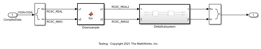
The model ex_reusable_csc contains the nonreusable subsystem DeltaSubsystem and the MATLAB Function block Downsample. DeltaSubsystem contains the MATLAB Function blocks DeltaX and DeltaY.
model ='ex_reusable_csc';
open_system(model);
Specify Reusable Storage Class in Code Mappings Editor
Open the Embedded Coder app.
To open the Code Mappings editor, click Code Interface > Individual Element Code Mappings.
In the model, select the
RCSC_REALsignal line. To view this signal or any signal in the Code Mappings editor, on the Signals/States tab, click the Add selected signals to code mappings button.For the row that represents the signal line, set the Storage Class column to
Reusable.Similary, add these signals to the Code Mappings editor and set Storage Class to
Reusable:
RCSC_IMAGRCSC_REAL2RCSC_IMAG2
And these signals inside the subsystem:
RCSC_REALRCSC_IMAGRCSC_REAL2RCSC_IMAG2
Alternatively, use these commands in the MATLAB® Command Window:
cmo = coder.mapping.utils.create(model);
cm = coder.mapping.api.get(model);

portHandles = get_param(...
    'ex_reusable_csc/Complex to Real-Imag','portHandles');
addSignal(cm,[portHandles.Outport(1),portHandles.Outport(2)],...
    'StorageClass','Reusable');

portHandles = get_param(...
    'ex_reusable_csc/Downsample','portHandles');
addSignal(cm,[portHandles.Outport(1),portHandles.Outport(2)],...
    'StorageClass','Reusable');

portHandles = get_param(...
    'ex_reusable_csc/DeltaSubsystem/DeltaX','portHandles');
addSignal(cm,[portHandles.Outport(1),portHandles.Outport(2)],...
    'StorageClass','Reusable');

portHandles = get_param(...
    'ex_reusable_csc/DeltaSubsystem/DeltaY','portHandles');
addSignal(cm,[portHandles.Outport(1),portHandles.Outport(2)],...
    'StorageClass','Reusable');
Build the model.
slbuild(model);
### Searching for referenced models in model 'ex_reusable_csc'.
### Total of 1 models to build.
### Starting build procedure for: ex_reusable_csc
### Successful completion of build procedure for: ex_reusable_csc

Build Summary

Top model targets:

Model            Build Reason                                         Status                        Build Duration
==================================================================================================================
ex_reusable_csc  Information cache folder or artifacts were missing.  Code generated and compiled.  0h 0m 45.469s

1 of 1 models built (0 models already up to date)
Build duration: 0h 0m 49.677s
For buffer reuse, the ex_reusable_csc.c file contains these global variables:
cfile = fullfile(pwd,...
    'ex_reusable_csc_ert_rtw','ex_reusable_csc.c');
coder.example.extractLines(cfile,...
    '/* Definition for custom storage class: Reusable */',...
    '/* External inputs (root inport signals with default storage) */',1,0);
/* Definition for custom storage class: Reusable */
static real_T RCSC_IMAG[1048576];      /* '<Root>/Complex to Real-Imag' */
static real_T RCSC_IMAG2[262144];      /* '<Root>/Downsample' */
static real_T RCSC_REAL[1048576];      /* '<Root>/Complex to Real-Imag' */
static real_T RCSC_REAL2[262144];      /* '<Root>/Downsample' */
The ex_reusable_csc.c file contains this code:
cfile = fullfile(pwd,...
    'ex_reusable_csc_ert_rtw','ex_reusable_csc.c');
coder.example.extractLines(cfile,...
    '/* Output and update for atomic system: ''<Root>/DeltaSubsystem'' */',...
    '/* Output and update for atomic system: ''<Root>/Downsample'' */',1,0);
coder.example.extractLines(cfile,...
    '/* Model step function */','/* Model initialize function */',1,0);
/* Output and update for atomic system: '<Root>/DeltaSubsystem' */
static void DeltaSubsystem(void)
{
  /* ComplexToRealImag: '<Root>/Complex to Real-Imag' incorporates:
   *  MATLAB Function: '<S1>/DeltaX'
   *  SignalConversion generated from: '<S1>/DeltaX'
   * */
  DeltaX(&RCSC_REAL2[0], &RCSC_IMAG2[0], &RCSC_REAL[0], &RCSC_IMAG[0]);

  /* SignalConversion generated from: '<Root>/Downsample' incorporates:
   *  ComplexToRealImag: '<Root>/Complex to Real-Imag'
   *  MATLAB Function: '<S1>/DeltaY'
   *  SignalConversion generated from: '<S1>/DeltaY'
   * */
  DeltaY(&RCSC_REAL[0], &RCSC_IMAG[0], &RCSC_REAL2[0], &RCSC_IMAG2[0]);
}

/* Model step function */
void ex_reusable_csc_step(void)
{
  int32_T i;

  /* ComplexToRealImag: '<Root>/Complex to Real-Imag' incorporates:
   *  Inport: '<Root>/ComplexData'
   */
  for (i = 0; i < 1048576; i++) {
    RCSC_REAL[i] = rtU.ComplexData[i].re;
    RCSC_IMAG[i] = rtU.ComplexData[i].im;
  }

  /* End of ComplexToRealImag: '<Root>/Complex to Real-Imag' */

  /* MATLAB Function: '<Root>/Downsample' */
  Downsample(&RCSC_REAL[0], &RCSC_IMAG[0], &RCSC_REAL2[0], &RCSC_IMAG2[0]);

  /* Outputs for Atomic SubSystem: '<Root>/DeltaSubsystem' */
  DeltaSubsystem();

  /* End of Outputs for SubSystem: '<Root>/DeltaSubsystem' */

  /* Outport: '<Root>/Out1' incorporates:
   *  RealImagToComplex: '<Root>/Real-Imag to Complex'
   *  SignalConversion generated from: '<S1>/DeltaY'
   * */
  for (i = 0; i < 261121; i++) {
    rtY.Out1[i].re = RCSC_REAL2[i];
    rtY.Out1[i].im = RCSC_IMAG2[i];
  }

  /* End of Outport: '<Root>/Out1' */
}
The variables RCSC_REAL and RCSC_IMAG hold the outputs of the Complex to Real-Image block and DeltaX. These variables hold the inputs to the DeltaY block. The variables RCSC_REAL2 and RCSC_IMAG2 hold the outputs of Downsample and DeltaY. These variables hold the inputs to the DeltaX block. By interleaving buffers in this way, you eliminate redundant data copies in the generated code.
To remove the signals from the Code Mappings editor, on the Signals/States tab, select the signals and click the Remove selected signals to code mappings button.
Alternatively, use these commands in the MATLAB Command Window:
portHandles = get_param(...
    'ex_reusable_csc/Complex to Real-Imag','portHandles');
removeSignal(cm,[portHandles.Outport(1),portHandles.Outport(2)]);

portHandles = get_param(...
    'ex_reusable_csc/Downsample','portHandles');
removeSignal(cm,[portHandles.Outport(1),portHandles.Outport(2)]);

portHandles = get_param(...
    'ex_reusable_csc/DeltaSubsystem/DeltaX','portHandles');
removeSignal(cm,[portHandles.Outport(1),portHandles.Outport(2)]);

portHandles = get_param(...
    'ex_reusable_csc/DeltaSubsystem/DeltaY','portHandles');
removeSignal(cm,[portHandles.Outport(1),portHandles.Outport(2)]);
When you generate code for the model, the ex_reusable_csc.h contains two extra global variables:
slbuild(model);
cfile = fullfile(pwd,...
    'ex_reusable_csc_ert_rtw','ex_reusable_csc.h');
coder.example.extractLines(cfile,...
    '/* Block signals and states',...
    '} D_Work;',1,0);
### Searching for referenced models in model 'ex_reusable_csc'.
### Total of 1 models to build.
### Starting build procedure for: ex_reusable_csc
### Successful completion of build procedure for: ex_reusable_csc

Build Summary

Top model targets:

Model            Build Reason                     Status                        Build Duration
==============================================================================================
ex_reusable_csc  Generated code was out of date.  Code generated and compiled.  0h 0m 19.332s

1 of 1 models built (0 models already up to date)
Build duration: 0h 0m 20.692s

/* Block signals and states (default storage) for system '<Root>' */
typedef struct {
  real_T z2[262144];                   /* '<S1>/DeltaY' */
  real_T z1[262144];                   /* '<S1>/DeltaY' */
  real_T z1_m[261632];                 /* '<S1>/DeltaX' */
  real_T z2_c[261632];                 /* '<S1>/DeltaX' */
  real_T RCSC_REAL[1048576];           /* '<Root>/Complex to Real-Imag' */
  real_T RCSC_IMAG[1048576];           /* '<Root>/Complex to Real-Imag' */
The ex_reusable_csc.c file now contains this code.
cfile = fullfile(pwd,...
    'ex_reusable_csc_ert_rtw','ex_reusable_csc.c');
coder.example.extractLines(cfile,...
    '/* Output and update for atomic system: ''<Root>/DeltaSubsystem'' */',...
    '/* Output and update for atomic system: ''<Root>/Downsample'' */',1,0);
coder.example.extractLines(cfile,...
    '/* Model step function */','/* Model initialize function */',1,0);
/* Output and update for atomic system: '<Root>/DeltaSubsystem' */
static void DeltaSubsystem(void)
{
  /* MATLAB Function: '<S1>/DeltaX' */
  DeltaX(rtDWork.z2, rtDWork.z1, rtDWork.z1_m, rtDWork.z2_c);

  /* MATLAB Function: '<S1>/DeltaY' */
  DeltaY(rtDWork.z1_m, rtDWork.z2_c, &rtDWork.z1[0], &rtDWork.z2[0]);
}

/* Model step function */
void ex_reusable_csc_step(void)
{
  int32_T i;

  /* ComplexToRealImag: '<Root>/Complex to Real-Imag' incorporates:
   *  Inport: '<Root>/ComplexData'
   */
  for (i = 0; i < 1048576; i++) {
    rtDWork.RCSC_REAL[i] = rtU.ComplexData[i].re;
    rtDWork.RCSC_IMAG[i] = rtU.ComplexData[i].im;
  }

  /* End of ComplexToRealImag: '<Root>/Complex to Real-Imag' */

  /* MATLAB Function: '<Root>/Downsample' */
  Downsample(rtDWork.RCSC_REAL, rtDWork.RCSC_IMAG, rtDWork.z2, rtDWork.z1);

  /* Outputs for Atomic SubSystem: '<Root>/DeltaSubsystem' */
  DeltaSubsystem();

  /* End of Outputs for SubSystem: '<Root>/DeltaSubsystem' */

  /* Outport: '<Root>/Out1' incorporates:
   *  RealImagToComplex: '<Root>/Real-Imag to Complex'
   */
  for (i = 0; i < 261121; i++) {
    rtY.Out1[i].re = rtDWork.z1[i];
    rtY.Out1[i].im = rtDWork.z2[i];
  }

  /* End of Outport: '<Root>/Out1' */
}
The generated code contains two additional global variables for holding block inputs and outputs.
Limitations for the Model That Use Reusable Storage Class in Code Mappings Editor
For reused data elements, you can specify the same value for the Identifier property. If you do not specify a value for the Identifier, the code generator uses the same signal label to name the reusable signal in the generated code. The code generator does not reuse signals if:
The signals have the same labels but different identifiers.
The signals have the same identifier but different values for these properties: DataScope, HeaderFile, DefinitionFile, and Owner. If there is a mismatch in any of the properties, the code generator stops and produces an error if the model configuration parameter Detect non-reused custom storage classes is set to
error.
Specify a Simulink Signal Object for Reuse
1. Open the model ReusableStorageClass.
model ='ReusableStorageClass';
open_system(model);

2. The signals in the model resolve to the corresponding Simulink.Signal data objects in the Base Workspace. Right-click on the RCSC_REAL signal line, and then click the Properties button. In the Signal Properties dialog box, inspect that the signal name is RCSC_REAL and the parameter Signal name must resolve to Simulink signal object is selected. This setting indicates that there is a Simulink.Signal data object in the Base Workspace with the same name as RCSC_REAL.
3. In the model, navigate into the DeltaSubsystem subsystem. Select the RCSC_REAL signal line in this subsystem. This signal also resolves to the signal object in the Base Workspace.
4. In the Base Workspace, double click the data object RCSC_REAL. The Simulink.Signal dialog box opens.
5. On the Code Generation tab, inspect that the Storage class parameter is set to Reusable. This setting instructs the code generator to generate code for the signal as a global variable named RCSC_REAL. With the Reusable storage class, the generated code can store the output of the Complex to Real-Imag block (at the root-level of the model) and the output of the MATLAB Function block DeltaX (in the subsystem) in the RCSC_REAL global variable.
6. In the Apps gallery, under Code Generation, click Embedded Coder. The C Code tab opens.
7. Click the Build button.
The generated code achieves the same results as the preceding workflow where you add signals to the Code Mappings editor and set Storage Class to Reusable.
Note: You can specify buffer reuse on signals that the code generator cannot implement. For those cases, use two diagnostics to specify the message type that the model displays. In the Configuration Parameters dialog box, these diagnostics are Detect non-reused custom storage classes and Detect ambiguous custom storage class final values.
bdclose(model)
Buffer Reuse for Unit Delay and Delay Blocks
To reuse the signal of a Unit Delay or Delay block, use the same reusable storage class specification for a pair of input and state arguments or a pair of output and state arguments of a Unit Delay or a Delay block. For Delay blocks, you must set the Delay length parameter to 1 and Initial condition > Source to Dialog. To access these parameters, in the model, open the Property Inspector and click the block in the model.
Limitations for Root Inport and Outport Signals
These limitations apply to a model in which you specify buffer reuse for a pair of root inport and outport signals:
The output ports cannot be conditional.
If the code generator cannot reuse the same buffer in a top model, the generated code contains additional buffers. If the top model is a referenced model, the code generator reports an error. To resolve the error, remove the
Simulink.Signalspecification from the signal that connects to the outport port.When you run the executable that the code generator produces, and you reuse a pair of root inport and outport signals, when the root input value is zero, the root output value must also be zero. If the output value is nonzero and you reuse the signals, then the results from the simulation can differ from the results that the executable produces.
There might be a simulation versus code generation mismatch when you assign the same Reusable storage class to pair of root inport and root outport signals. This mismatch occurs when an Assignment block drives the Root Outport block, and the Assignment block does not assign a value to every element of the output signal because the Y port of the Assignment block is not active. This image shows a model in which the mismatch occurs:

During simulation, the unwritten Assignment block output values are zero. During code generation, the unwritten output values are the same as the input.
Limitations for the Model That Use Simulink Signal Object
These limitations apply to a model in which you specify buffer reuse for signals by using a Simulink.Signal data object:
Signals that you specify for reuse must have the same data types and sampling rates.
For user-specified buffer reuse, blocks that modify a signal specified for reuse must execute before blocks that use the original signal value. Sometimes the code generator has to change the block operation order so that buffer reuse can occur. For models in which the code generator is unable to reorder block operations, buffer reuse does not occur.
For models in which the code generator reorders block operations so that
Simulink.Signalreuse can occur, you can observe the difference in the sorted order. On the Debug tab, in the Diagnostics section select the Information Overlays drop-down arrow. In the Blocks section of the dialog, select Execution Order. To display the sorted execution order during simulation, on the Modeling tab, select Update Model. To display the execution order in the generated code, on the C Code tab, select Build Model.You can specify buffer reuse for a chain of reusable subsystems as long as these subsystems do not get reused anywhere in the model.