Get Started with Cosimulation Wizard for MATLAB System Object
Using HDL Verifier™, you can set up cosimulation between MATLAB® or Simulink® and an HDL simulator. The Cosimulation Wizard is a graphical user interface (GUI) that takes HDL code as input and generates a cosimulation block or System object™ as output. The System object allows cosimulating HDL within MATLAB, and the block allows cosimulating HDL within Simulink.
The example design is a Fast Fourier Transform (FFT) of size 8 written in Verilog®. The FFT is commonly used in digital signal processing applications to produce frequency distribution of a signal.
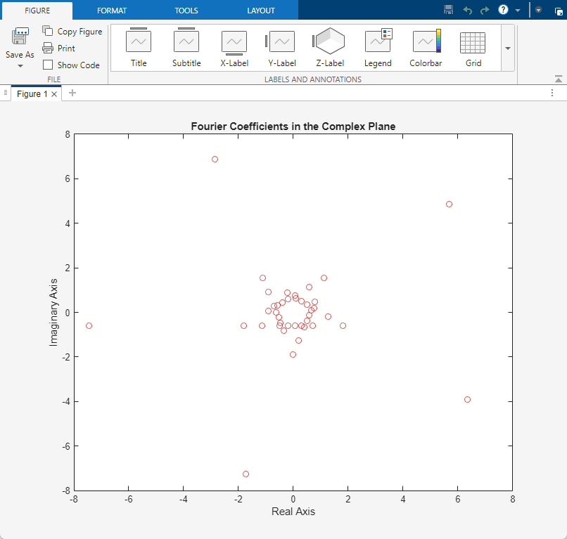
To verify the correctness of this FFT, a MATLAB System object testbench is provided. This testbench generates a periodic sinusoidal input to the HDL design under test (DUT) and plots the Fourier Coefficients in the Complex plane.
The Cosimulation Wizard takes the Verilog file as its input. It also collects other inputs pertaining to the HDL code for setting up cosimulation in each step. At the end of the example, the Cosimulation Wizard generates a MATLAB script that instantiates a configured HDL Cosimulation System object, a MATLAB script that compiles the HDL design, and a MATLAB script that launches the HDL simulator for cosimulation.
This example uses a MATLAB System object and one of the following HDL simulators to cosimulate and verify a register transfer level (RTL) design.
Vivado® Simulator from AMD®
ModelSim™ or Questa™ from Siemens EDA
Xcelium™ from Cadence®
VCS® from Synopsys®
1. Launch Cosimulation Wizard
Launch the Cosimulation Wizard tool by executing this command in MATLAB.
cosimWizard
2. Specify Cosimulation Type
On the Cosimulation Type page, perform the following steps:
a. If you are using ModelSim, set HDL Simulator to ModelSim.

If you are using Xcelium, set HDL Simulator to Xcelium.
If you are using Vivado Simulator, set HDL Simulator to Vivado Simulator.
If you are using VCS, set HDL Simulator to VCS.
b. Set HDL cosimulation to MATLAB System Object.
c. Do not change the default Use HDL simulator executables on the system path option if the HDL simulator executables appear on your system path. If these executable do not appear on the path, specify the HDL simulator path.
d. Click Next.
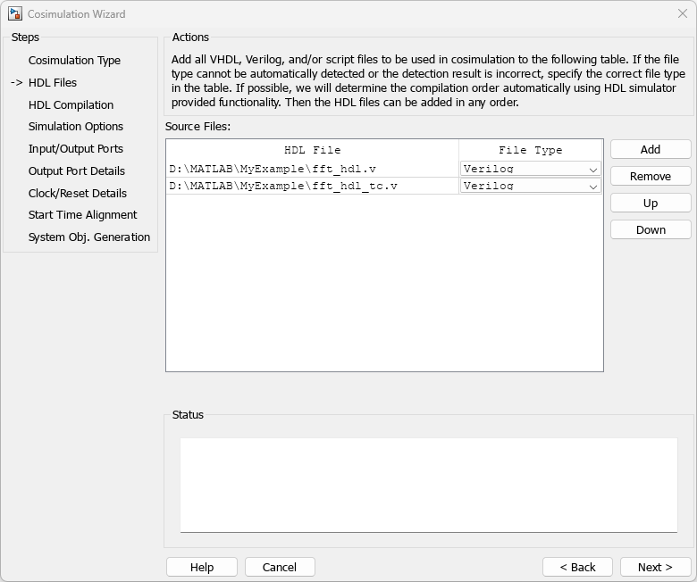
3. Select HDL Files
On the HDL Files page, perform the following steps:
a. Add HDL files to the file list:
For ModelSim, Xcelium, and Vivado Simulator
Click Add and select the Verilog files fft_hdl.v and fft_hdl_tc.v in your example folder.
Review the files in the file list to make sure the file type is correctly identified.
For VCS
Click Add and select the Verilog files fft_hdl.v and fft_hdl_tc.v in your example folder.
Select fft_hdl.v as Top-Level module.
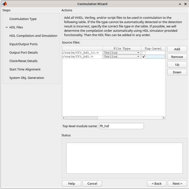
b. Click Next.
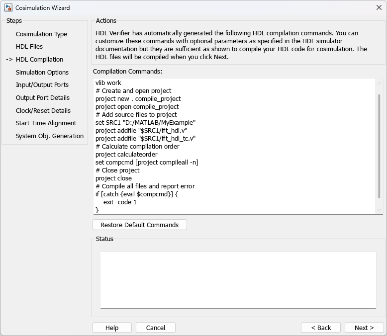
4. Specify HDL Compilation Commands
The Cosimulation Wizard lists the default commands in the Compilation Commands window. For this example, you do not need to change these commands.
Compilation commands for the ModelSim follow.
For VCS, the compilation and simulation steps are combined. Specify compilation options for VHDL or Verilog, elaboration options, or simulation options in this step. You can specify a parameter file or leave it blank for the wizard to create one with default values. You can edit the file to override default parameter values. Click next to specify inputs and outputs.

Click Next. The MATLAB console displays the compilation log. If an error occurs during compilation, that error appears in the Status area. Correct the error before proceeding to the next step.
5. Select HDL Modules for Cosimulation
This step is not applicable for VCS.
On the Simulation Options page, perform the following steps:
a. Specify the name of the HDL module or entity for cosimulation.
For ModelSim and Xcelium
From the list, select fft_hdl. This module is the Verilog module you use for cosimulation. If you do not see fft_hdl in the list, enter the file name manually.
The Simulation options for the ModelSim follow.

For Vivado Simulator
For the Vivado simulator, name of Verilog module is selected by default. The Simulation options for Vivado simulator follow.

b. Click Next. The Cosimulation Wizard launches the HDL simulator in the background console using the specified HDL module and simulation options. When the wizard launches the HDL simulator successfully, the wizard populates the input and output ports on the Verilog model fft_hdl and displays them in the next step.
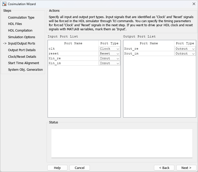
6. Specify Input/Output Port Types
In this step, the Cosimulation Wizard displays two tables containing the input and output ports of fft_hdl, respectively.
The Cosimulation Wizard attempts to correctly identify the port type for each port. If the wizard incorrectly identifies a port, you can change the port type using these tables.
For input ports, you can select
Clock,Reset,Input, orUnused. HDL Verifier connects only the input ports markedInputto MATLAB during cosimulation.HDL Verifier connects output ports marked
Outputwith MATLAB during cosimulation. The link software and MATLAB ignore those output ports markedUnusedduring cosimulation.You can change the parameters for signals identified as
ClockandResetin a later step.
For this example, accept the default port types and click Next.
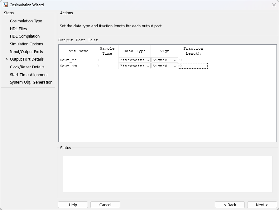
7. Specify Output Port Details
For this example, the HDL FFT outputs are signed, 13 bits long with 9 bits of fraction length. On the Output Port Details page, perform the following steps:
a. Note that the Sample Time cannot be changed and is always fixed to 1 when you use the HdlCosimulation System object.
b. Set the Data Type to Fixedpoint for both outputs.
c. Set the Sign to Signed for both inputs.
d. Set the Fraction Length to 9 for both outputs.
e. Click Next.
8. Set Clock and Reset Details
Set the clock period (ns) to 20. The Verilog code indicates that the reset is synchronous and the active value is 1. You can reset the entire HDL design at time 1 ns, triggered by the rising edge of the clock. Use a duration of 15 ns for the reset signal. On the Clock/Reset Details page, perform the following steps:
a. Set the clock period to 20.
b. Set the active edge to Rising.
c. Set the reset initial value to 1.
d. Set the reset signal duration to 15.
Click Next.

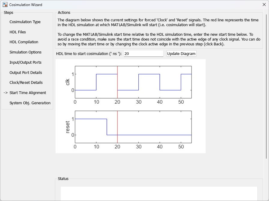
9. Confirm Start Time Alignment
The Start Time Alignment page displays a plot for the waveforms of clock and reset signals. The Cosimulation Wizard indicates the HDL time to start cosimulation with a red line. The start time is also the time at which the System object gets the first input sample from the HDL simulator. The active edge of the clock is a rising edge. Thus, at time 20 ns in the HDL simulator, the registered output of the FFT is stable. No race condition exists and the default HDL time to start cosimulation (20 ns) is correct.
Click Next.
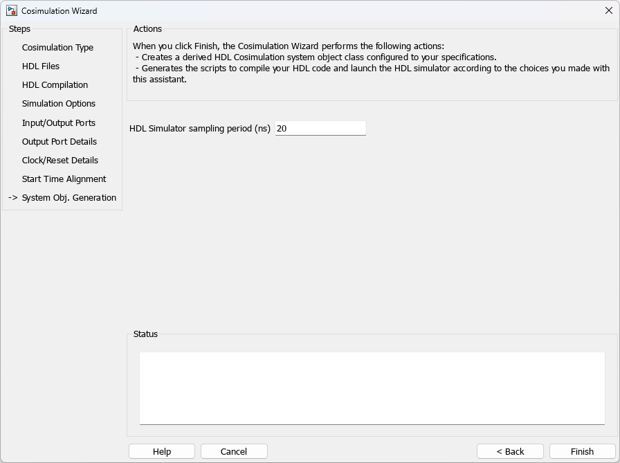
10. Generate System Object
Before the Cosimulation Wizard generates the scripts, you have the option to modify the HDL Simulator sampling period. The sampling period determines the time in the HDL Simulator that elapses between each call to step in MATLAB. The sampling period is typically equal to the clock period. You can also specify if your inputs and outputs are frame based (instead of sample based).
Click Finish to complete the Cosimulation Wizard session.
11. Create Testbench to Verify HDL Design
For this example, you can use the testbench script fft_tb.m provided with the example.
After you click Finish in the Cosimulation Wizard, the application generates three MATLAB scripts in the current directory.
For ModelSim, Xcelium, and VCS
compile_hdl_design_fft_hdl.m: To compile the HDL design.
launch_hdl_simulator_fft_hdl.m: Launches the MATLAB System object server and starts the HDL simulator.
hdlcosim_fft_hdl.m: Creates the HdlCosimulation System object.
For Vivado Simulator
hdlverifier_compile.m: Compiles the HDL design.
hdlverifier_gendll_fft_hdl.m: Creates a compiled shared library containing the HDL design and simulation kernel integrated into the behavior of the System object.
hdlcosim_fft_hdl.m: Creates the HdlCosimulation System object.
Open the files fft_tb.m and hdlcosim_fft_hdl.m, located in the same directory as the Verilog files, and observe the HdlCosimulation System object calls. hdlcosim_fft_hdl.m contains the HdlCosimulation instantiation and fft_tb.m contains a MATLAB System object testbench. Use this testbench to verify the HDL design for the corresponding HdlCosimulation System object.
12. Run Cosimulation and Verify HDL Design
For ModelSim, Xcelium, and VCS
Compile the HDL design by executing the script compile_hdl_design_fft_hdl.m.
Launch the HDL simulator by executing the script launch_hdl_simulator_fft_hdl.m.
When the HDL simulator is ready, return to MATLAB and start the simulation by executing the script fft_tb.m.
For Vivado Simulator
Start the simulation by executing the script fft_tb.m.
Verify the result from the plot in the testbench. The plot displays the Fourier coefficients in the complex plane.