Frame-Based HDL Cosimulation
Frame-based processing can improve the computation time of your Simulink® models because it processes multiple samples at once. The frame-based signals also let you simulate the behavior of frame-based systems more realistically. With the HDL Cosimulation block, you can build cosimulation models that take advantage of frame-based processing through frame-based cosimulation.
Frame-Based Processing with HDL Cosimulation
In frame-based processing, a frame of data is a collection of consecutive samples from a single channel or multiple channels. One frame of a single-channel signal is represented by an M-by-1 column vector, and one frame of an N-channel signal is represented by an M-by-N matrix, where M is the number of samples per frame. A signal is frame-based if it is propagated through a model one frame at a time.
Frame-based cosimulation is supported only for Simulink. For a Simulink model that uses frame-based processing with HDL Cosimulation, the behavior of the HDL code does not change during simulation in the HDL simulator. Simulink assumes that the HDL simulator processing is sample-based. In frame mode, the HDL Cosimulation block transmits frame-based input data from Simulink to the HDL simulator, which unpacks and processes the signal one sample at a time. Then, the HDL Cosimulation block assembles sample-based output from the HDL simulator into frames as required for Simulink processing.
This image demonstrates how HDL Cosimulation interprets a frame of data from Simulink in frame-based mode:
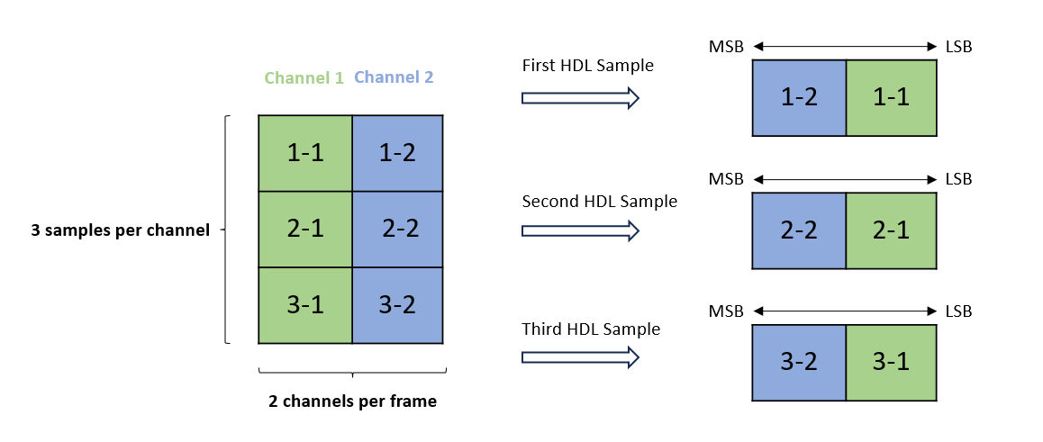
A frame of data from Simulink is shown on the left as a 3-by-2 matrix, where 2 is the number of Simulink signal channels and 3 is the number of samples per channel. HDL Cosimulation represents each sample (row) of the matrix as an HDL sample with a single HDL element. For HDL elements with bit width less than or equal to 128 bits, the number of signal channels must be 1. For HDL elements with bit width greater than 128 bits, the number of signal channels can be greater than 1.
To use frame-based processing with HDL Cosimulation, connect one or more Simulink signals to one or more input ports of the HDL Cosimulation block. The HDL Cosimulation block configures the output signals at the same frame sizes as those of the inputs. Depending on the HDL Word Length of your HDL design, HDL Cosimulation represents the Simulink signals at the HDL ports in the following ways:
HDL Word Length is less than or equal to 128 bits:
Input ports – The signal data type and dimension of the input ports are inherited from the driving signal. Configure your driving signal with a single signal channel. Each frame of the input signal is an M-by-1 vector, where M is the number of samples per frame and 1 is the number of signal channels. In this case, the HDL Word Length must match the Simulink Word Length.
Output ports – HDL Cosimulation creates output ports for frame data of size M-by-1, where M is the number of samples per frame for one signal channel. Every HDL word is represented as a Simulink word.
HDL Word Length is greater than 128 bits:
Input ports – The signal data type and dimension of the input ports are inherited from the driving signals. Configure your driving signals with multiple signal channels. Each frame of the input signal is an M-by-N matrix, where M is the number of samples per frame and N is the number of signal channels. The number of signal channels is determined by the data type of the Simulink driving signal and your HDL design. For example:
When HDL Word Length = 150 and Simulink Word Length = 50, HDL Verifier allows a Simulink port with data width of 50 bits and number of signal channels N = 3.
When HDL Word Length = 140 and Simulink Word Length = 50, HDL Verifier allows a Simulink port with data width of 50 bits and number of signal channels N = 3. HDL Verifier packs 150 bits of Simulink into 140 bits of HDL. HDL Verifier ignores the 10 most significant bits (MSB) of the last Simulink word.
Output ports – HDL Verifier creates a vector of Simulink ports to process frame data of size M-by-N', where M is the number of samples per frame and N' is the number of signal channels. N' is determined by your HDL design. For example:
When HDL Word Length = 150 and Simulink Word Length = 50, HDL Verifier creates a Simulink port with data width of 50 bits and number of channels N' = 3.
When HDL Word Length = 150 and Simulink Word Length = 60, HDL Verifier creates a Simulink port with data width of 60 bits and number of channels N' = 3. Since the HDL word has only 150 bits, but the Simulink port requires 180 bits, 30 bits of the last Simulink word are extended according to the Sign extended.
Frame-Based Processing Requirements and Restrictions
When connecting Simulink signals to an HDL Cosimulation block, all signals connected to the block must have the same frame size.
Frame-based processing in the Simulink model is transparent to the operation of the HDL model under simulation in the HDL simulator. The HDL model is presumed to be sample-based. The following constraints also apply to the HDL model:
In Simulink, specify HDL signals as scalar values.
In MATLAB®, specify HDL signals as scalar values or as a row or column vector of characters, with one bit per character.
For more information about the data types supported by MATLAB and HDL Verifier™, see Supported Data Types.
Frame-Based Cosimulation Example
This example shows how to use the HDL Cosimulation block to cosimulate a VHDL® implementation of a simple lowpass filter. In the example, you compare the performance of the simulation using frame-based and sample-based signals.
This tutorial is specific to ModelSim™ users. However, much of the process is the same for Xcelium™ users.
Design Files
The filter in the model is imported from existing HDL code. The example uses the data file mtlb.mat as an input signal. This file contains a speech signal. The sample data is of data type double, sampled at a rate of 8 kHz. To load and view the model, enter the following commands at the MATLAB® command prompt.
open_system("frame_filter_cosim.slx")
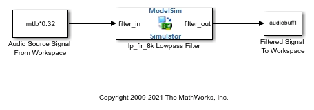
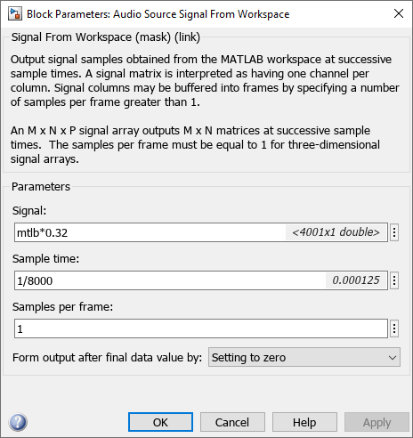
The Audio Source Signal From Workspace block provides an input signal from the workspace variable mtlb. The block is configured for an 8 kHz sample rate, with a frame size of 80, as shown in this figure.

The sample rate and frame size of the input signal propagate throughout the model.
The VHDL code file lp_fir_8k.vhd implements a simple lowpass FIR filter with a cutoff frequency of 1500 Hz. The HDL Cosimulation block simulates this HDL module. The HDL Cosimulation block ports and clock signal are configured to match the corresponding signals on the VHDL entity.
For the ModelSim simulation to execute the desired behavior, the clk_enable signal of the lp_fir_8k entity must be forced high. To force the signal, the HDL Cosimulation block transmit a presimulation command. The command is in the Simulation pane of the HDL Cosimulation block, as shown in the following figure (example shown for use with ModelSim).

The HDL Cosimulation block returns the output in the workspace variable audiobuff1 via the Filtered Signal To Workspace block.
Run Cosimulation
After opening the model, perform the following steps:
1. Load the source speech signal, which you filter later, into the MATLAB workspace.
load mtlb
If you have a compatible sound card, you can play the source signal by typing the following commands at the MATLAB command prompt:
a = audioplayer(mtlb,8000);
play(a);
2. Make sure you have ModelSim on the path, and start the simulator by entering the following command at the MATLAB command prompt:
vsim
The ModelSim window opens.
3. At the ModelSim prompt, create a design library and compile the VHDL filter code from the source file lp_fir_8k.vhd by typing the following commands:
vlib work
vcom lp_fir_8k.vhd
4. The VHDL entity lp_fir_8k defines the lowpass filter. At the ModelSim prompt, load the instantiated entity lp_fir_8k for cosimulation:
vsimulink lp_fir_8k
ModelSim is now set up for cosimulation.
5. In MATLAB, run a simulation and measure elapsed time as follows:
tic; sim(gcs); toc
The timing in this code excerpt is typical for a run of this model given a simulation stop time of 1 second and a frame size of 80 samples. Timings are system-dependent and vary slightly from one simulation run to the next.
Note the timing you obtained. For the next simulation run, you can change the model to sample-based operation and compare the length of simulation.
6. MATLAB stores the filtered audio signal returned from ModelSim in the workspace variable audiobuff1. If you have a compatible sound card, you can play the filtered signal to hear the effect of the lowpass filter. Play the signal by typing the following commands at the MATLAB command prompt:
b = audioplayer(audiobuff1,8000);
play(b);
7. Open the block mask of the Audio Source Signal From Workspace block and set the Samples per frame parameter to 1, as shown in this figure. Then click OK.
8. Select the Simulink window. On the Modeling tab, in the Compile section, click Update Model.
Now the source signal (and all signals inheriting from it) is a scalar.
9. Restart ModelSim. At the ModelSim prompt, enter:
restart
10. In MATLAB, run a simulation and measure elapsed time as follows:
tic; sim(gcs); toc
Observe that the elapsed time has increased significantly with a sample-based input signal. The timing in this code excerpt is typical for a sample-based run of this model given a simulation stop time of 1 second. Timings are system-dependent and vary slightly from one simulation run to the next.
Close the simulation in an orderly way: in ModelSim, stop the simulation by selecting Simulate > End Simulation. Then, close the Simulink model window.