Turbine (2P)
Libraries:
Simscape /
Fluids /
Two-Phase Fluid /
Fluid Machines
Description
The Turbine (2P) block models a turbine in a two-phase fluid network. You can parameterize the block as a tabulated turbine map that is either a 1-D function of pressure ratio or 2-D function of pressure ratio and corrected mass flow rate. Fluid flowing from port A to port B generates torque. Port R reports shaft torque and angular velocity relative to port C, which represents the turbine casing.
When enabled, port VN represents the nozzle opening fraction. This
value linearly scales the corrected mass flow rate but does not influence the turbine
efficiency. A value of 1 corresponds to the data in the turbine map.
The Turbine (2P) block assumes that superheated fluid enters the inlet. You can use the Report when fluid at inlet is not fully vapor parameter to choose what the block does when the fluid does not meet superheated conditions.
Turbine Map
To visualize the block map, in the block dialog box, click the Plot button next to Turbine map. Each time you modify the block settings, click Reload Data on the figure window.
The turbine map relates turbine performance, as a function of pressure ratio, to the corrected mass flow rate and isentropic efficiency. The pressure ratio is the ratio between the turbine inlet pressure and outlet pressure.
The turbine map plots two separate graphs: corrected mass flow rate versus pressure
ratio and isentropic efficiency versus pressure ratio. When you set the Turbine
map parameterization to Tabulated data - flow rate and efficiency
vs. corrected speed and pressure ratio, the plots also depend on the
corrected rotor speed, N. The indexing variable β does not need to be the
same between the mass flow rate and efficiency tables.
Due to the large changes in pressure and temperature inside a turbine, the turbine map plots performance in terms of the corrected mass flow rate. The block adjusts the corrected mass flow rate from the inlet mass flow rate by using a corrected pressure and temperature
where:
A is the mass flow rate at port A.
TA is the temperature at port A.
Tcorr is the Reference temperature for corrected flow parameter. Refer to the data sheet for your turbine for this value.
corr is the corrected mass flow rate.
When Turbine map parameterization is
Analytical - nominal pressure ratio and corrected mass flow
                  rate
, this is the value of the Nominal corrected mass flow rate parameter.When Turbine map parameterization is
Tabulated
                  data - Flow rate and efficiency vs. pressure ratio
, this is the value of the Corrected mass flow rate vector, mdot(pr) parameter.When Turbine map parameterization is
Tabulated
                  data - Flow rate and efficiency vs. corrected speed and pressure
                  ratio
, this is the value of the Corrected mass flow rate table, mdot(N,beta) parameter.pA is the pressure at port A.
pcorr is the Reference pressure for corrected flow parameter. Refer to the data sheet for your turbine for this value.
The block also adjusts the shaft speed, ω, according to the reference temperature, such that the corrected shaft speed is
Shaft Torque
The block calculates the shaft torque, τ, as
where:
Δhtotal is the total change in the fluid specific enthalpy.
ηm is the value of the Mechanical efficiency parameter.
ω is the relative shaft angular velocity, ωR - ωC.
Reversed flow, from port B to port A, is outside of the typical turbine operation mode and may not return accurate results. A threshold region when flow approaches zero ensures the block generates no torque when the flow rate is near zero or reversed.
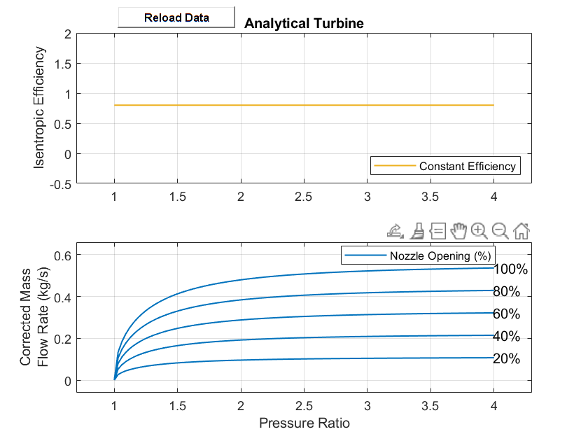
Analytical Parameterization
Use the analytical parametrization to create a turbine based on the expected nominal
operating conditions. When Turbine map parameterization is
Analytical – nominal pressure ratio and corrected mass flow
          rate
, the turbine isentropic efficiency is constant and the mass flow rate
is a function of the pressure ratio.
This image shows the default turbine map when you use the analytical parameterization.
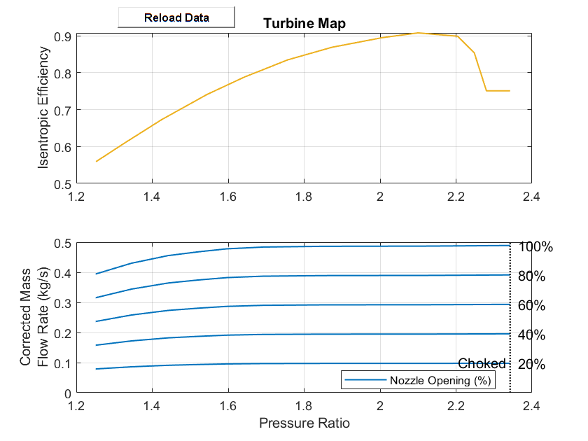
Parameterization by Pressure Ratio
When Turbine map parameterization is Tabulated data -
Flow rate and efficiency vs. pressure ratio, the turbine isentropic
efficiency and mass flow rate are a function of the pressure ratio and do not account for
any changes in the turbine rotational speed.
The last element of the Corrected mass flow rate vector, mdot(pr) and the Pressure ratio vector, pr parameters represents the corrected mass flow rate and pressure ratio at choked flow conditions.
This image shows the default turbine map when you use the 1-D parameterization.
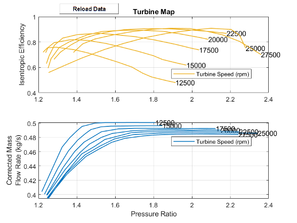
Parameterization by Pressure Ratio and Corrected Mass Flow Rate
When Turbine map parameterization is set to Tabulated
data - Flow rate and efficiency vs. corrected speed and pressure ratio, the
turbine isentropic efficiency, pressure ratio, and corrected mass flow rate are a function
of the corrected speed, N, and the map index, β. The
block uses linear interpolation between data points for the efficiency, pressure ratio, and
corrected mass flow rate parameters.
The last column of the Corrected mass flow rate table, mdot(N,beta) and the Pressure ratio table, pr(N,beta) represent the corrected mass flow rate and pressure ratio at choked flow conditions.
This image shows the default turbine map when you use the 2-D parameterization.
Continuity Equations
Mass is preserved over the block:
where B is the mass flow rate at port B.
The block calculates the energy balance as
where:
ΦA is the energy flow rate at port A.
ΦB is the energy flow rate at port B.
Pfluid is the work done by the fluid, which the block determines from the change in total fluid specific enthalpy,
Assumptions and Limitations
The shaft does not rotate under reversed flow conditions. Results during reversed flows may not be accurate.
Examples

Liquid Air Energy Storage System
Models a grid-scale energy storage system based on cryogenic liquid air. When there is excess power, the system liquefies ambient air based on a variation of the Claude cycle. The cold liquid air is stored in a low-pressure insulated tank until needed. When there is high power demand, the system expands the stored liquid air to produce power based on the Rankine cycle.
Ports
Input
Conserving
Parameters
References
[1] Kurzke, Joachim. "How to Get Component Maps for Aircraft Gas Turbine Performance Calculations." Volume 5: Manufacturing Materials and Metallurgy; Ceramics; Structures and Dynamics; Controls, Diagnostics and Instrumentation; Education; General, American Society of Mechanical Engineers, 1996, p. V005T16A001.
[2] Plencner, Robert M. “Plotting component maps in the Navy/NASA Engine Program (NNEP): A method and its usage.” NASA Technical Memorandum, 1989.