Determine Power Losses and THD for PWM Methods
This example calculates the inverter power loss and total harmonic distortion (THD) in motor current for different pulse-width modulation (PWM) methods. The example uses field-oriented control (FOC) algorithm that runs a permanent-magnet synchronous motor (PMSM) in speed control mode as a reference. The example only supports simulation.
The example model simulates the PWM methods sequentially in this order:
1. SPWM — sinusoidal PWM
2. SVM — space vector modulation
3. 60 DPWM — 60 degree discontinuous PWM
4. 60 DPWM (+30 degree shift) — +30 degree shift from 60 DPWM
5. 60 DPWM (-30 degree shift) — -30 degree shift from 60 DPWM
6. 30 DPWM — 30 degree discontinuous PWM
7. 120 DPWM — Positive DC component
8. 120 DPWM — Negative DC component
The model simulates each method for a fixed time period before changing the PWM method. You can configure this time period by updating the variable Ts_MethodDuration available in the model initialization script associated with the example model. For instructions to locate the model initialization script, see Estimate Control Gains and Tune Control Parameters.
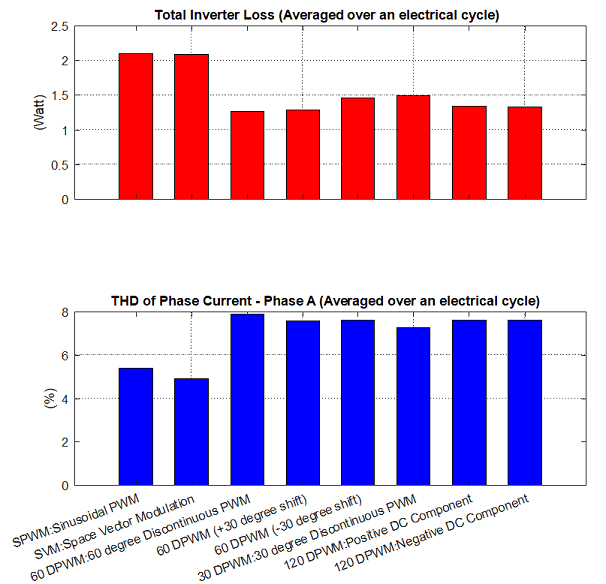
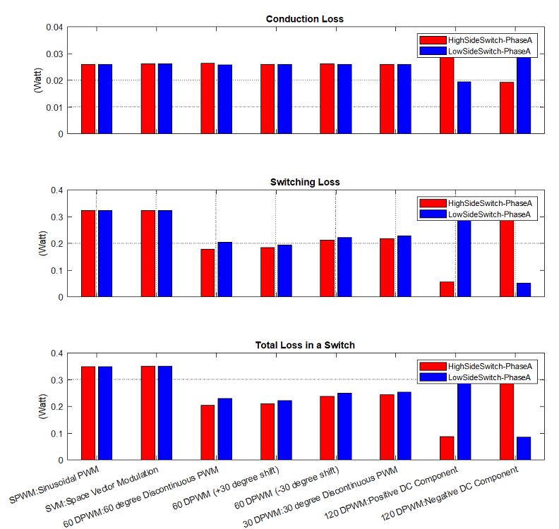
After the simulation completes, the script mcb_InverterLossTHDExtract.m uses the simulation data available in the MATLAB® workspace to generate the power loss in the inverter switches and motor current THD plots for the different PWM methods.
Note: The inverter's MOSFET used in this example are configured using the datasheet of MOSFETs available in the Texas Instruments® BOOSTXL-DRV8305 board.
Model
The example includes the mcb_inverter_powerloss model.
You can use this model only for simulation.

Required MathWorks Products
Motor Control Blockset™
Simscape™ Electrical™
Prerequisites
1. Obtain the motor parameters. The Simulink® model uses default parameters that you can replace with values from either the motor datasheet or other sources.
However, if you have the motor control hardware, you can estimate the parameters for the motor that you want to use by using the Motor Control Blockset parameter estimation tool. For instructions, see Estimate Motor Parameters Using Motor Control Blockset Parameter Estimation Tool. The parameter estimation tool updates the motorParam variable (in the MATLAB workspace) with the estimated motor parameters.
2. Update the motor and inverter parameters in the model initialization script associated with the Simulink model. For instructions, see Estimate Control Gains and Tune Control Parameters.
Update the motor parameters in the PMSM block available in the mcb_inverter_powerloss/Inverter and Motor - Plant Model/Motor subsystem of the example model. In addition, update the parameters of the MOSFET available in mcb_inverter_powerloss/Inverter and Motor - Plant Model/Inverter/Switch1 (mcb_ref_switchmodel) of the example model.
3. Configure the simulation time period for the PWM methods using the Ts_MethodDuration variable available in the model initialization script associated with the example model. Ensure that this time period is long enough for the speed control loop to stabilize and enable the motor to reach a steady speed state.
Simulate Model
This example supports simulation. Follow these steps to simulate the model.
1. Open the model included with this example.
2. Click the Simulate hyperlink (step 2) available in the Explore More section of the example model to run the simulation. Alternatively, you can simulate the example model by clicking Run on the Simulation tab, however, ensure that you do not interrupt the simulation process.
Note: The simulation takes few minutes to complete. If you interrupt the simulation process, the example does not compute and plot the power loss and THD information.
After the simulation completes, the model stores the simulation data in the MATLAB workspace that is used by the mcb_InverterLossTHDExtract.m script to extract the power loss and THD information and plot them for the different PWM methods. After generating the plots, the script saves the power loss and THD information in the LossTHDdata variable (in the MATLAB workspace).
3. You can also click the function hyperlink available in the Explore more section of the model, to view the mcb_InverterLossTHDExtract.m script that computes the power loss and THD information and generates the plots.
You can use this example to analyze and determine a suitable PWM technique for your motor control application.
Note:
The example algorithm averages the power loss and THD information of a PWM method over the last electrical cycle (among a series of cycles) corresponding to that PWM method.
When speeds are greater than 0.75 per-unit, the controllers may get saturated for sinusoidal PWM (SPWM) method. Therefore, in such cases, the results of SPWM will not be comparable with other methods.
These are the examples of the plots generated by the model: