Quadrature Decoder
Compute position of quadrature encoder
Libraries:
Motor Control Blockset /
Sensor Decoders
Motor Control Blockset HDL Support /
Sensor Decoders
Description
The Quadrature Decoder block computes the position of the quadrature encoder.
To calculate the angular position of the quadrature encoder (and the rotor) in either degrees, radians, or per-unit, the block uses one of the following methods.
Difference between current encoder counter value and encoder counter value at the previous index pulse (when index pulse is available).
Current encoder counter value (when index pulse is not available).
This figure shows a quadrature encoder disk with two channels (QEPA and QEPB) and an index pulse (QEPI):

In this example, the timer driven by the QEP increments by four for each slit:

Equations
The block computes the angular position (in counts) of the quadrature encoder using the
Cnt and Idx block inputs:
When Cnt ≥ Idx:
When Cnt < Idx:
When Cnt (an unsigned integer) exceeds the maximum value of the
selected counter size, the block adds the necessary compensation internally.
When you clear the External index count checkbox, only
Cnt input is available, therefore:
where:
is the angular position of the quadrature encoder in counts.
is the number of counts in one rotation cycle of the quadrature encoder (Counts per revolution = Encoder slits ⨯ Encoder counts per slit).
The block computes the output θm as:
Where, MaxPosition = 360 (degrees) or 2π (radians) or 1 (per-unit), based on the selected value of the Position unit parameter.
Examples
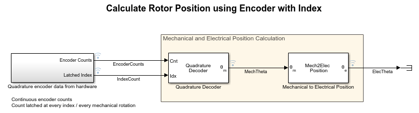
Simulate Calculation of Rotor Position Using Quadrature Decoder Block
Use the quadrature decoder block to simulate estimation of rotor position.

Quadrature Encoder Offset Calibration for PMSM
Calculates the offset between the d-axis of the rotor and encoder index pulse position as detected by the quadrature encoder sensor. The control algorithm (available in the field-oriented control and parameter estimation examples) uses this offset value to compute an accurate and precise position of the d-axis of rotor. The controller needs this position to implement the field-oriented control (FOC) correctly in the rotor flux reference frame (d-q reference frame), and therefore, run the permanent magnet synchronous motor (PMSM) correctly.

Field-Oriented Control of PMSM Using Quadrature Encoder
Implements the field-oriented control (FOC) technique to control the speed of a three-phase permanent magnet synchronous motor (PMSM). The FOC algorithm requires rotor position feedback, which is obtained by a quadrature encoder sensor. For details about FOC, see Field-Oriented Control.
Ports
Input
Output
Parameters
Extended Capabilities
Version History
Introduced in R2020a