Main Content

patternElevation

System object: phased.HeterogeneousConformalArray
Namespace: phased

Plot heterogeneous conformal array directivity or pattern versus elevation

Syntax

patternElevation(sArray,FREQ)
patternElevation(sArray,FREQ,AZ)
patternElevation(sArray,FREQ,AZ,Name,Value)
PAT = patternElevation(___)

Description

patternElevation(sArray,FREQ) plots the 2-D array directivity pattern versus elevation (in dBi) for the array sArray at zero degrees azimuth angle. When AZ is a vector, multiple overlaid plots are created. The argument FREQ specifies the operating frequency.

The integration used when computing array directivity has a minimum sampling grid of 0.1 degrees. If an array pattern has a beamwidth smaller than this, the directivity value will be inaccurate.

patternElevation(sArray,FREQ,AZ), in addition, plots the 2-D element directivity pattern versus elevation (in dBi) at the azimuth angle specified by AZ. When AZ is a vector, multiple overlaid plots are created.

patternElevation(sArray,FREQ,AZ,Name,Value) plots the array pattern with additional options specified by one or more Name,Value pair arguments.

PAT = patternElevation(___) returns the array pattern. PAT is a matrix whose entries represent the pattern at corresponding sampling points specified by the 'Elevation' parameter and the AZ input argument.

Input Arguments

expand all

Heterogeneous conformal array, specified as a phased.HeterogeneousConformalArray System object.

Example: sArray= phased.HeterogeneousConformalArray;

Frequency for computing directivity and pattern, specified as a positive scalar. Frequency units are in hertz.

  • For an antenna or microphone element, FREQ must lie within the range of values specified by the FrequencyRange or the FrequencyVector property of the element. Otherwise, the element produces no response and the directivity is returned as –Inf. Most elements use the FrequencyRange property except for phased.CustomAntennaElement and phased.CustomMicrophoneElement, which use the FrequencyVector property.

  • For an array of elements, FREQ must lie within the frequency range of the elements that make up the array. Otherwise, the array produces no response and the directivity is returned as –Inf.

Example: 1e8

Data Types: double

Azimuth angles for computing sensor or array directivities and patterns, specified as a 1-by-N real-valued row vector where N is the number of desired azimuth directions. Angle units are in degrees. The azimuth angle must lie between –180° and 180°.

The azimuth angle is the angle between the x-axis and the projection of the direction vector onto the xy plane. This angle is positive when measured from the x-axis toward the y-axis.

Example: [0,10,20]

Data Types: double

Name-Value Arguments

Specify optional pairs of arguments as Name1=Value1,...,NameN=ValueN, where Name is the argument name and Value is the corresponding value. Name-value arguments must appear after other arguments, but the order of the pairs does not matter.

Before R2021a, use commas to separate each name and value, and enclose Name in quotes.

Displayed pattern type, specified as the comma-separated pair consisting of 'Type' and one of

  • 'directivity' — directivity pattern measured in dBi.

  • 'efield' — field pattern of the sensor or array. For acoustic sensors, the displayed pattern is for the scalar sound field.

  • 'power' — power pattern of the sensor or array defined as the square of the field pattern.

  • 'powerdb' — power pattern converted to dB.

Example: 'powerdb'

Data Types: char

Signal propagation speed, specified as the comma-separated pair consisting of 'PropagationSpeed' and a positive scalar in meters per second.

Example: 'PropagationSpeed',physconst('LightSpeed')

Data Types: double

Array weights, specified as the comma-separated pair consisting of 'Weights' and an M-by-1 complex-valued column vector. Array weights are applied to the elements of the array to produce array steering, tapering, or both. The dimension M is the number of elements in the array.

Note

Use complex weights to steer the array response toward different directions. You can create weights using the phased.SteeringVector System object or you can compute your own weights. In general, you apply Hermitian conjugation before using weights in any Phased Array System Toolbox™ function or System object such as phased.Radiator or phased.Collector. However, for the directivity, pattern, patternAzimuth, and patternElevation methods of any array System object use the steering vector without conjugation.

Example: 'Weights',ones(10,1)

Data Types: double
Complex Number Support: Yes

Elevation angles, specified as the comma-separated pair consisting of 'Elevation' and a 1-by-P real-valued row vector. Elevation angles define where the array pattern is calculated.

Example: 'Elevation',[-90:2:90]

Data Types: double

Handle to the axes along which the array geometry is displayed specified as a scalar.

Output Arguments

expand all

Array directivity or pattern, returned as an L-by-N real-valued matrix. The dimension L is the number of elevation angles determined by the 'Elevation' name-value pair argument. The dimension N is the number of azimuth angles determined by the AZ argument.

Examples

expand all

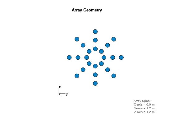
Construct a 24-element disk array using elements with two different types of cosine antennas. Then, plot the array elevation directivity pattern.

Create the array

The array consists of cosine antenna elements with different power exponents.

sElement1 = phased.CosineAntennaElement('CosinePower',1.5);
sElement2 = phased.CosineAntennaElement('CosinePower',1.8);
N = 8;
azang = (0:N-1)*360/N-180;
p0 = [zeros(1,N);cosd(azang);sind(azang)];
posn = [0.6*p0, 0.4*p0, 0.2*p0];
sArray = phased.HeterogeneousConformalArray(...
    'ElementPosition',posn,...
    'ElementNormal', zeros(2,3*N),...
    'ElementSet',{sElement1,sElement2},...
    'ElementIndices',[1 1 1 1 1 1 1 1,...
    1 1 1 1 1 1 1 1,...
    2 2 2 2 2 2 2 2]);

View the disk array

viewArray(sArray)

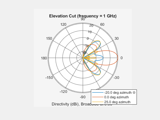
Plot the power pattern

Plot the elevation power pattern of this array for three different azimuth angles: 0, -20 and 25 degrees. Apply radial tapering to the array. Assume the operating frequency is 1 GHz and the wave propagation speed is the speed of light.

c = physconst('LightSpeed');
fc = 1e9;
wts = [0.5*ones(N,1); 0.7*ones(N,1); 1*ones(N,1)];
wts = wts/sum(abs(wts));
patternElevation(sArray,fc,[-20,0,25],'PropagationSpeed',c,...
    'Type','directivity','Weights',wts)

More About

expand all

Version History

Introduced in R2015a