Synthesizing Gapped LFM Waveform with Spectral Mask Requirements
This example shows how to synthesize a wideband gapped Linear Frequency Modulated (LFM) waveform with spectral mask requirements for operation in congested RF environments. We first generate a gapped LFM waveform that does not meet the requirements and then apply the mask using the shapespectrum function to generate a waveform that can be transmitted in the allocated frequency bands [1].
Introduction
Spectral coexistence between radar and communications systems continues to be an area of active investigation. In Spectrum Sharing Using Spectrum Sensing and Waveform Notching, we showcase how a cognitive radar system could operate in a shared radar and communications environment where the spectral location of the communications system is variable and unknown beforehand.
In other cases, radar systems are allocated certain predefined portions of the frequency spectrum. These regions can be discontinuous due to the operation of communications systems within neighboring regions, and a radar system may want to transmit across these discontinuous regions for the performance improvements that come with wideband operation. In this case, there are requirements on what power level cannot be exceeded across the spectrum that the system is operating in, but there are not exact requirements on the nature of the radar waveform.
In this example, a radar system is operating in the region from 2200 to 3000 MHz. This region is largely but not entirely allocated to radiolocation according to the U.S. Frequency Allocation Chart [2]. The radar system is subject to the following general spectral mask requirements to ensure minimal interference with neighboring radio systems:
The shape of the sensing waveform frequency spectrum should have a roll-off from -55 dB to -35 dB in the out of band emission region according to the National Telecommunications and Information Administration Spectrum Standards [3].
The power contained in any spectral component in the inaccessible regions of the occupied frequency spectrum must be at least 35 dB lower than the power contained in the accessible regions of the frequency spectrum. We assume that the system has full access to bands allocated for radiolocation in the U.S. Frequency Allocation Chart. This gives the system access to 2305-2385 MHz, 2417-2483.5 MHz, and 2700-3000 MHz.
These requirements are coded below and a plot illustrates these requirements.
% Define spectral mask requirement 1 - roll off
rollOffFloor = -55;
rollOffCeil = -35;

% Define spectral mask requirement 2 - accessible bands
noAccessSuppression = -35;
accessibleBands = [2305e6,2385e6;...
                   2417e6,2483.5e6
                   2700e6,3000e6];
fMin = accessibleBands(1,1)-200e6;
fMax = accessibleBands(end,2)+200e6;
fc = mean([fMin,fMax]);

% Plot the requirements
helperPlotMask(accessibleBands,rollOffFloor,rollOffCeil,noAccessSuppression,fMin,fMax);

The radar system is free to transmit a radar waveform that is compliant with this spectral mask regardless of other waveform properties. Therefore, it is up to the radar system designer to decide what other properties are important. In this example, we require that our final radar waveform is constant amplitude to minimize transmit distortion and has time-frequency characteristics that resemble that of an LFM waveform which has many desirable properties.
This example goes over the following two part process for generating such a waveform:
Generate an initial gapped LFM waveform using
phased.LinearFMWaveformthat is not compliant with the required spectral mask.Use the shapespectrum function to apply the desired spectral mask to the initial gapped LFM waveform, forcing spectral compliance.
The purpose of this example is to illustrate how to generate a radar waveform with desirable frequency spectrum properties. In other cases, we may want to synthesize radar waveforms based on other important characteristics. For example, in Generate Novel Radar Waveforms Using GAN, we look at how we can generate waveforms with desired ambiguity functions.
Generating the Initial Gapped LFM Requirements
In order to generate the initial gapped LFM waveform, we repeatedly use phased.LinearFMWaveform within each of the accessible bands and stitch each separate LFM together. We set our sample rate to be our total bandwidth, and arbitrarily collect enough samples so that our smallest accessible band contains 200 waveform samples.
fs = fMax-fMin;
smallestBand = min(accessibleBands(:,2)-accessibleBands(:,1));
ns = ceil(fs / smallestBand * 200);
We set the ramp rate so that the ramp is constant over all the accessible bands.
totalBandwidth = sum(accessibleBands(:,2)-accessibleBands(:,1));
rampTime = ns / fs;
rampRate = totalBandwidth/rampTime;
We then loop through each band and used the phased.LinearFMWaveform to generate a separate LFM.
initialLFM = zeros(ns,1);
nBands = size(accessibleBands,1);
startIdx = 1;
for i = 1:nBands
    % Calculate LFM parameters
    bandStart = accessibleBands(i,1);
    bandStop = accessibleBands(i,2);
    bandWidth = bandStop-bandStart;
    nSamples = ceil((bandWidth/rampRate)*fs);
    pulseWidth = nSamples/fs;
    prf = 1/pulseWidth;
    fOffset = bandStart-fMin;

    % Create LFM
    currentLFM = phased.LinearFMWaveform(SampleRate=fs,...
                                   PulseWidth=pulseWidth,...
                                   PRF=prf,...
                                   SweepBandwidth=bandWidth,...
                                   FrequencyOffset=fOffset);

    % Stitch new LFM to previous LFMs to create gapped LFM
    sig = currentLFM();
    lastIdx = startIdx+nSamples-1;
    if lastIdx > ns
        nRemove = lastIdx-ns;
        sig = sig(1:end-nRemove);
        lastIdx = ns;
    end
    initialLFM(startIdx:lastIdx) = sig;
    startIdx = lastIdx+1;
end
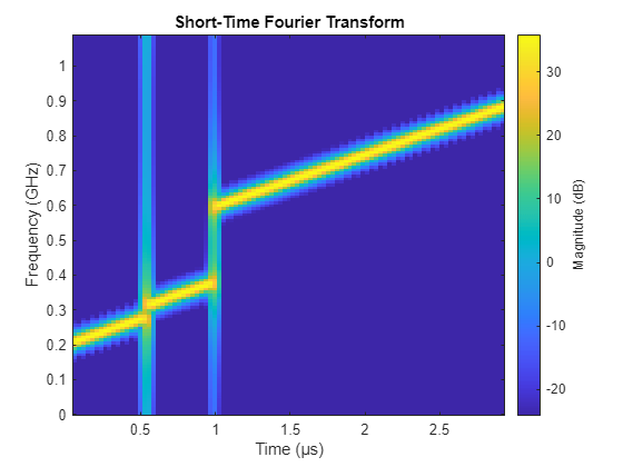
The short time Fourier Transform (STFT) of the initial waveform shows the gapped LFM behavior we desired, but also shows significant spectral leakage into the non-accessible frequency bands, meaning that interference with systems accessing these adjacent bands is likely.
figure; stft(initialLFM,fs,FrequencyRange="twosided");
Applying the Spectral Mask to the Gapped LFM Waveform
Based on these requirements, we build the required waveform spectral mask with the required roll-off at the beginning of the spectral mask as well as the notches in the unavailable regions of the frequency spectrum.
% Get frequency vector
freqs = linspace(0,fMax-fMin,ns);

% Initialize spectral mask
fPeak = mag2db(max(abs(fft(initialLFM))));
spectralMask = ones(ns,1)*noAccessSuppression+fPeak;

% Create initial roll-off
fInit = accessibleBands(1,1)-fMin;
rollInRegion = freqs < fInit;
spectralMask(rollInRegion) = linspace(rollOffFloor+fPeak,rollOffCeil+fPeak,sum(rollInRegion));

% Create accessible bands
nBands = size(accessibleBands,1);
for iBand = 1:nBands
    fAccess = freqs >= (accessibleBands(iBand,1)-fMin) & (freqs <= accessibleBands(iBand,2)-fMin);
    spectralMask(fAccess) = Inf;
end

% Create final roll-off
fFinal = accessibleBands(end,2)-fMin;
rollOutRegion = freqs > fFinal;
spectralMask(rollOutRegion) = linspace(rollOffCeil+fPeak,rollOffFloor+fPeak,sum(rollInRegion));
The desired spectrum input to shapespectrum contains the spectral mask as the allowable upper limit, and the lower limit is set to be all -Inf, meaning that no lower limit need be applied.
desiredSpectrum = [-Inf(ns,1),spectralMask];
As stated in the introduction, we require that our samples are all unit amplitude to allow for low distortion transmission at maximum amplifier power levels.
requiredMagnitude = ones(ns,1);
Now that we have generated the initial gapped LFM, the desired spectrum with the spectral mask as the upper limit, and the required magnitude, we can use the shapespectrum function to apply the spectral mask requirements.
% Generate and plot waveform with mask requirements
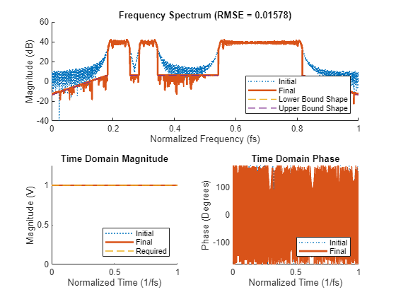
shapespectrum(desiredSpectrum,initialLFM,Magnitude=requiredMagnitude);
We can see that the final waveform is a phased-coded waveform with constant normalized envelope that closely matches the spectral mask requirements.
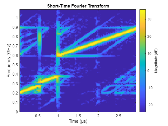
By once again plotting the STFT below, we can see that the waveform becomes slightly distorted but retains the time-frequency characteristics of the original gapped LFM waveform.
% Plot stft of the spectrally compliant waveform
gappedLFM = shapespectrum(desiredSpectrum,initialLFM,Magnitude=requiredMagnitude);
figure; stft(gappedLFM,fs,FrequencyRange="twosided");

Conclusion
By first generating a gapped LFM waveform, and then applying the desired spectral requirements to this waveform using the shapespectrum function, we are able to generate a waveform with similar time frequency properties to the original gapped LFM that meets our spectral requirements. This approach can be used to generate novel sensing waveforms in spectrally congested environments.
References
[1] Rowe et al. Spectrally Constrained Waveform Design. SP Tips & Tricks. 2014.
[2] National Telecommunications and Information Administration. U.S. Frequency Allocation Chart. 2003.
[3] National Telecommunications and Information Administration. National Spectrum Requirements, Chapter 5, Spectrum Standards. 2021.
function helperPlotMask(accessibleBands,rollOffFloor,rollOffCeil,noAccessSuppression,fMin,fMax)
    % initialize the frequencies and corresponding frequencies
    fScale = 1e6;
    accessibleBands = accessibleBands/fScale;
    fMin = fMin/fScale;
    fMax = fMax/fScale;
    rollOffEnd = accessibleBands(1,1);
    freqs = [fMin rollOffEnd];
    mask = [rollOffFloor rollOffCeil];

    % create polyregions
    ymin = -70;
    rolloffregion = polyshape([fMin fMin rollOffEnd rollOffEnd],[rollOffFloor ymin ymin rollOffCeil]);
    accessregion = polyshape;
    noaccessregion = polyshape;

    % add freqs and mask for each band
    nBands = size(accessibleBands,1);
    for iBand = 1:nBands
        fStart = accessibleBands(iBand,1);
        fStop = accessibleBands(iBand,2);
        if iBand == nBands
            fNext = fMax;
        else
            fNext = accessibleBands(iBand+1,1);
        end

        % update regions
        accessregion = accessregion.addboundary([fStart fStart fStop fStop],[ymin 0 0 ymin]);
        if iBand < nBands
            % update mask line
            freqs = [freqs fStart fStart fStop fStop fNext];
            mask = [mask noAccessSuppression 0 0 noAccessSuppression noAccessSuppression];
            noaccessregion = noaccessregion.addboundary([fStop fStop fNext fNext],[ymin noAccessSuppression noAccessSuppression ymin]);
        else
            freqs = [freqs fStart fStart fStop fStop];
            mask = [mask noAccessSuppression 0 0 noAccessSuppression];
        end
    end

    rolloffstart = fStop;
    freqs = [freqs rolloffstart fMax];
    mask = [mask rollOffCeil rollOffFloor];
    rolloffregion = rolloffregion.addboundary([rolloffstart rolloffstart fMax fMax],[rollOffCeil ymin ymin rollOffFloor]);

    ax = axes(figure);
    hold(ax,"on");
    plot(ax,freqs,mask,DisplayName="Spectral Mask Upper Limits",LineWidth=2);
    plot(ax,accessregion,DisplayName="Access Region",EdgeAlpha=0,FaceColor=[50/255 205/255 50/255]);
    plot(ax,noaccessregion,DisplayName="No Access Region",EdgeAlpha=0,FaceColor=[255/255 255/255 0/255]);
    plot(ax,rolloffregion,DisplayName="Roll Off Region",EdgeAlpha=0,FaceColor=[220/255 20/255 60/255]);
    title(ax,"Required Waveform Spectral Mask");
    ylabel(ax,"Magnitude (dB)");
    xlabel(ax,"Frequency (MHz)")
    ylim(ax,[ymin 10]);
    xlim(ax,[fMin fMax])
    legend(ax,Location="southeast");
end
See Also
shapespectrum | phased.LinearFMWaveform