Interference Mitigation Using Frequency Agility Techniques
This example shows how to model frequency agility techniques to counter the effects of interference in radar, communications, and electronic warfare (EW) systems. This example uses Simulink® to create a scenario with a ground-based radar and an approaching aircraft that can also emit jamming signals. For a similar example using MATLAB®, see Frequency Agility in Radar, Communications, and EW Systems.
Introduction
In this model, a phased array radar is designed to detect an approaching aircraft. The aircraft is equipped with a jammer which can intercept the radar signal and transmit a spoofing signal back to confuse the radar. On the other hand, the radar system is capable of transmitting a waveform with different operating frequencies to mitigate the jamming effect. The model includes blocks for waveform generation, signal propagation, and radar signal processing. The example shows how the radar and jammer interact and gain advantage over each other.

The radar is operating at 300 MHz with a sampling rate of 2 MHz. The radar is located at the origin and is assumed to be stationary. The target is located about 10 km away and approaching at approximately 100 meters per second.
Waveform Generation
The Waveform Generation subsystem includes a pulse waveform library containing a linear frequency modulated (LFM) waveform with different configurations. By varying the input index to the pulse waveform library using the Hopping Band Constant block, a frequency hopped waveform at a shifted center frequency is generated. You can use the Hopping Band Selector rotary switch to change the hopping band. Therefore, the radar system is capable of switching the transmit waveform either following a fixed schedule or when it detects jamming signals. This example assumes that the waveform can be generated for four different frequencies, referred to as center band and hopped bands 1 through 3. The center band is the subband around the carrier frequency, and the hopped bands are the subbands located quarter bandwidth above the carrier.

Propagation Channels
The signal propagation is modeled for both the forward channel and the return channel. Once the transmitted signal hits the target aircraft, the reflected signal travels back to the radar system via the return channel. In addition, the jammer analyzes the incoming signal and sends back a jamming signal to confuse the radar system. That jamming signal is also propagated through the return channel. Because different signals can occupy different frequency bands, wideband propagation channels are used.
Signal Processing
The radar receives both the target return and the jamming signal. Upon receiving the signal, a Channelizer block is used to extract the signal from different bands. In this example, the Channelizer uses four bands to extract the signal from the center band and the hopped bands. The signal in each band then passes through the corresponding matched filter to improve the signal-to-noise ratio (SNR) and be ready for detection.

Exploring the Example
Several parameters of the model are calculated by the helper function helperslexFrequencyAgilityParam. To open the function from the model, click the Modify Simulation Parameters block. This function is executed once when the model is loaded. It exports to the workspace a structure whose fields are referenced by the dialog boxes. To modify any parameters, either change the values in the structure at the command prompt or edit the helper function and rerun it to update the parameter structure.
Results and Displays
First run the model for the case when there is no jamming signal. The scope shows that there is one strong echo in the center band with a delay of approximately 67 microseconds, which corresponds to a target range of 10 km. Therefore, the target is correctly detected. Meanwhile, there are no returns detected in the hopped bands 1 through 3.

The Waveform Spectrum spectrum analyzer shows the center band waveform spectrum. The Received Spectrum spectrum analyzer show that the received signal occupies the center band.


Now enable the jammer by clicking the Jammer Switch block. In this situation, the target intercepts the signal, amplifies it, and then sends it back with a delay corresponding to a different range. As a result, the scope now shows two returns in the center band. The true target return is still at the old position, but the ghost return generated by the jammer appears stronger and closer to the radar, so the radar is likely to be confused and assign precious resource to track this fake target.

Note that both the jammer signal and the target return are in the center band, as shown in the Received Spectrum spectrum analyzer.

If the radar has a preset frequency hopping schedule or is trained to know that it might have been confused by a jamming signal, it can switch to a different frequency band to operate. You can simulate such by moving the Hopping Band Selector Rotary Switch block from position 1 to position 2 so the radar signal is transmitted in the hopped band.

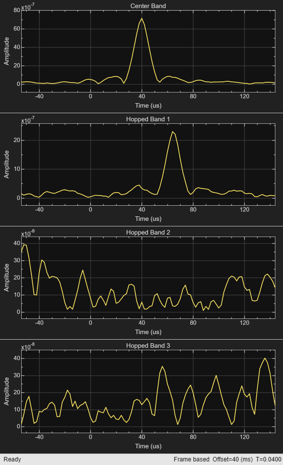
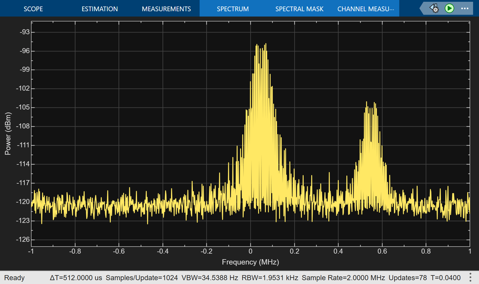
Because the radar now operates in the hopped band, the target echo is also in the hopped band. From the scope, the target echo is at the appropriate delay in the hopped band 1. Meanwhile, the jammer is yet to figure out the new operating band of the radar so the jamming signal still appears in the center band. Yet the jamming signal can no longer fool the radar.
The Received Spectrum spectrum analyzer shows that the received signal now occupies two bands.
Summary
This example models a radar system detecting a target equipped with a jammer. It shows how frequency agility techniques can be used to mitigate the jamming effect.