Design DDR5 IBIS-AMI Models to Support Back-Channel Link Training
This example shows how to create transmitter and receiver AMI models that support link training communication (back-channel) using a similar method as the one defined in the IBIS 7.0 specification by adding to the library blocks in SerDes Toolbox™. This example uses a DDR5 write transfer (Controller to SDRAM) to demonstrate the setup.
Introduction
IBIS 7.0 introduced the ability for models to perform link training, or auto-negotiation, by providing a mechanism for the Tx and Rx AMI executable models to communicate during GetWave operation. A link training algorithm can either emulate what the silicon is doing, or it can use channel analysis methods to determine the optimal Tx and Rx equalization settings, then lock in those settings for the remainder of the simulation.
Communications between the Tx and Rx executable models are in messages that both the Tx and Rx executable models understand, and the EDA tool does not need to understand. These agreed upon messages are called a Back-Channel Interface Protocol. The IBIS specification does not describe the details of the Back-Channel Interface Protocol but only a method to make the communication work. This example shows you how to generate a new protocol named DDRx_Write.
Currently, SerDes Toolbox does not support the IBIS-AMI back-channel interface reserved parameters directly. Instead, it supports model specific parameters, which have _ST appended to their name, that perform a similar function. Since these model specific parameters do not use the same name as the reserved parameters from the IBIS specification, they must be used either as a matched set or with other back-channel models developed by SerDes Toolbox that support the same protocol. These models should work well in any industry standard AMI model simulator.
DDR5 Tx/Rx IBIS-AMI Model Setup in SerDes Designer App
The first part of this example starts with the DDR5 controller transmitter model from DDR5 Controller Transmitter/Receiver IBIS-AMI Model and the SDRAM receiver AMI model from DDR5 SDRAM Transmitter/Receiver IBIS-AMI Model. This example uses a few additional pass-through blocks to support the back-channel communication. You can export the model to Simulink® for further customization.
Open the model DDR5_Write_txrx_ami by typing the following command in the MATLAB® command window:
>> serdesDesigner('DDR5_Write_txrx_ami')

For a write transaction, the transmitter (Tx) is a DDR5 controller using 3-tap feed forward equalization (FFE), while the receiver (Rx) is using a variable gain amplifier (VGA) with 7 pre-defined settings and a 4-tap decision feedback equalizer (DFE) with built-in clock data recovery. To support this configuration the SerDes System is set up as follows:
Configuration Setup
Symbol Time is set to
208.3ps, since the target operating rate is4.8Gbps for DDR5-4800.Target BER is set to
100e-18.Signaling is set to
Single-ended.Samples per Symbol and Modulation are kept at default values, which are
16andNRZ(nonreturn to zero), respectively.
Transmitter Model Setup
The Pass-Through block Tx_BCI is a block used to support this back-channel implementation. The operation of this block will be described later in this example.
The Tx FFE block is set up for one pre-tap, one main-tap, and one post-tap by including three tap weights. This is done with the array [0 1 0], where the main tap is specified by the largest value in the array. Tap ranges will be added later in the example when the model is exported to Simulink.
The Tx AnalogOut model is set up so that Voltage is
1.1V, Rise time is100ps, R (output resistance) is50 ohms, and C (capacitance) is0.65pF. The actual analog models used in the final model will be generated later in this example.
Channel Model Setup
Channel loss is set to
5dB, which is typical of DDR channels.Single-ended impedance is set to
40ohms.Target Frequency is set to
2.4GHz, which is the Nyquist frequency for 4.8 GHz.
Receiver Model Setup
The Rx AnalogIn model is set up so that R (input resistance) is
40ohms and C (capacitance) is0.65pF. The actual analog models used in the final model will be generated later in this example.The Pass-Through block
Rx_BCI_Readis a block used to support this back-channel implementation. The operation of this block will be described later in this example.The VGA block is set up with a Gain of 1 and the Mode set to
on. Specific VGA presets will be added later in this example after the model is exported to Simulink.The DFECDR block is set up for four DFE taps by including four Initial tap weights set to 0. The Minimum tap value is set to
[-0.2 -0.075 -0.06 -0.045]V, and the Maximum tap value is set to[0.05 0.075 0.06 0.045]V. The DFE has been configured to use 2x tap weights in order to be consistent with the JEDEC DFE tap definition.The Pass-Through block
Rx_BCI_Writeis a block used to support this back-channel implementation. The operation of this block will be described later in this example.
Export SerDes System to Simulink
Click the Export button to export the configuration to Simulink for further customization and generation of the AMI model executables.
DDR5 Tx/Rx IBIS-AMI Model Setup in Simulink
This part of the example takes the SerDes system exported by the SerDes Designer app and customizes it as required for DDR5 back-channel operation in Simulink.
Review Simulink Model Setup
The SerDes System imported into Simulink consists of Configuration, Stimulus, Tx, Analog Channel, and Rx blocks. All the settings from the SerDes Designer app are transferred to the Simulink model. Save the model and review each block setup.
Inside the Tx subsystem, double-click the FFE block to open the FFE Block Parameters dialog box. Expand the IBIS-AMI parameters and clear the Mode parameter, effectively hard-coding the current value of Mode in the final AMI model to
Fixed.Inside the Rx subsystem, double-click the VGA block to open the VGA Block Parameters dialog box. The Mode and Gain settings are carried over from the SerDes Designer app.
Inside the Rx subsystem, double-click the DFECDR block to open the DFECDR Block Parameters dialog box. The Initial tap weights, Minimum DFE tap value, and Maximum tap value RMS settings are carried over from the SerDes Designer app. The Adaptive gain and Adaptive step size are set to
3e-06and1e-06, respectively, which are reasonable values based on DDR5 SDRAM expectations. Expand the IBIS-AMI parameters and clear the Phase offset and Reference offset parameters, effectively hard-coding these parameters to their current values.
Update Transmitter (Tx) AMI Parameters
Open the AMI-Tx tab in the SerDes IBIS-AMI Manager dialog box. The reserved parameters are listed first followed by the model-specific parameters adhering to the format of a typical AMI file.
Set the pre-emphasis tap: Edit TapWeights -1 and set Format to
Range, Typ to0, Min to-0.2, and Max to0.2.Set the main tap: Edit TapWeights 0 and set Format to
Range, Typ to1, Min to0.6, and Max to1.Set the post-emphasis tap: Edit TapWeights 1 and set Format to
Range, Typ to0, Min to-0.2, and Max to0.2.
Create New Tx Back-Channel AMI Parameters
To support back-channel operation, additional control parameters are needed. In the AMI-Tx tab in the SerDes IBIS-AMI Manager dialog box, highlight Tx_BCI and add the following 6 new parameters:
FFE_Tapm1: This parameter creates a Data Store that is used to pass the FFE pre tap value between Tx blocks during training. Click the Add Parameter… button. Set Parameter Name to
FFE_Tapm1, Current Value to0, Usage toInOut, Type toFloat, and Format toValue. Set the Description as:Tx FFE Tap -1 for back-channel training. Click OK to save the changes and note that this automatically creates Data Stores in the Tx_BCI PassThrough block.FFE_Tap0: This parameter creates a Data Store that is used to pass the FFE main tap value between Tx blocks during training. Click the Add Parameter… button. Set Parameter Name to
FFE_Tap0, Current Value to0, Usage toInOut, Type toFloat, and Format toValue. Set the Description as:Tx FFE Tap 0 for back-channel training. Save the changes.FFE_Tap1: This parameter creates a Data Store that is used to pass the FFE post tap value between Tx blocks during training. Click the Add Parameter… button. Set Parameter Name to
FFE_Tap1, Current Value to0, Usage toInOut, Type toFloat, and Format toValue. Set the Description as:Tx FFE Tap 1 for back-channel training. Save the changes.BCI_Protocol_ST: This parameter is only used to generate a parameter named BCI_Protocol_ST in the .ami file for partial compliance to the IBIS-AMI specification. This parameter is not used by this model. Click the Add Parameter… button. Set Parameter Name to
BCI_Protocol_ST, Current Value to "DDRx_Write"(with quotes), Usage toInfo, Type toString, and Format toValue. Set the Description as:This model supports the DDRx_Write Example back-channel protocol. NOTE: This model does not currently support the reserved parameter BCI_Protocol as an input to the model.Save the changes.BCI_ID_ST: This parameter is only used to generate a parameter named BCI_ID_ST in the .ami file for partial compliance to the IBIS-AMI specification. This parameter is not used by this model. Click the Add Parameter… button. Set Parameter Name to
BCI_ID_ST, Current Value to"bci_comm" (with quotes), Usage toInfo, Type toString, and Format toValue. Set the Description as:This model creates files with names beginning with 'bci_comm' for back-channel communication. NOTE: This model does not currently support the AMI reserved parameter BCI_ID as an input to the model.Save the changes.BCI_State_ST: This parameter creates a Data Store that is used to communicate the status of back-channel training: 1=Off, 2=Training, 3=Converged, 4=Failed, 5=Error. Click the Add Parameter… button. Set Parameter Name to
BCI_State_ST, Usage toInOut, Type toInteger, and Format toList. Set the Description as:Back channel training status. NOTE: This model does not currently support the AMI reserved parameter BCI_State as an input to the model.Set the Default to2, List values to[1 2 3 4 5], and List_Tip values to["Off" "Training" "Converged" "Failed" "Error"],then set the Current Value to"Training". Save the changes.
Update Receiver (Rx) AMI Parameters
On the AMI-Rx tab in the SerDes IBIS-AMI Manager dialog box, the reserved parameters are listed first followed by the model-specific parameters adhering to the format of a typical AMI file.
Set the VGA gain: Edit Gain. Set Description as:
Rx Amplifier Gain. Make sure Format is set toListand set Default to1. Set List values as[0.5 0.631 0.794 1 1.259 1.585 2]and List_Tip values as["-6 dB" "-4 dB" "-2 dB" "0 dB" "2 dB" "4 dB" "6 dB"], then set the Current Value to0dB. Click OK to save the changes.Set the first DFE tap weight: Edit TapWeights 1. Make sure Format is set to
Rangeand set Typ =0, Min =-0.2, and Max =0.05. Save the changes.Set the second DFE tap weight: Edit TapWeights 2. Make sure Format is set to
Rangeand set Typ =0, Min =-0.075, and Max =0.075. Save the changes.Set the third DFE tap weight: Edit TapWeights 3. Make sure Format is set to
Rangeand set Typ =0, Min =-0.06, and Max =0.06. Save the changes.Set the fourth DFE tap weight: Edit TapWeights 4. Make sure Format is set to
Rangeand set Typ =0, Min =-0.045, and Max =0.045. Save the changes.
Create New Rx Back-Channel AMI Parameters
To support back-channel operation, additional control parameters are needed. In the AMI-Rx tab in the SerDes IBIS-AMI Manager dialog box, highlight Rx_BCI_Write and add the following new parameters (Note: Rx_BCI_Read does not require any additional parameters):
sampleVoltage: This parameter creates a Data Store that will be used to pass the CDR sample voltage to the other Rx blocks during training. Click the Add Parameter… button. Set Parameter Name to
sampleVoltage, Current Value to0, Usage toInOut, Type toFloat, and Format toValue. Set the Description as:Sample Voltage for back-channel training. Click OK to save the change and note that this automatically creates Data Stores in the Rx_BCI_Write PassThrough block.BCI_Protocol_ST: This parameter only generates a parameter named BCI_Protocol_ST in the .ami file for partial compliance to the IBIS-AMI specification. This parameter is not used by this model. Click the Add Parameter… button. Set Parameter Name to
BCI_Protocol_ST, Current Value to "DDRx_Write"(with quotes), Usage toInfo, Type toString, and Format toValue. Set the Description as:This model supports the DDRx Write Example back-channel protocol. NOTE: This model does not currently support the AMI reserved parameter BCI_Protocol as an input to the model. Save the changes.BCI_ID_ST: This parameter only generates a parameter named BCI_ID_ST in the .ami file for partial compliance to the IBIS-AMI specification. This parameter is not used by this model. Click the Add Parameter… button. Set Parameter Name to
BCI_ID_ST, Current Value to "bci_comm" (with quotes), Usage toInfo, Type toString, and Format toValue. Set the Description as: This model creates files with names beginning with 'bci_comm' for back-channel communication. NOTE: This model does not currently support the reserved parameter BCI_ID as an input to the model. Save the changes.BCI_State_ST: This parameter creates a Data Store that is used to communicate the status of back-channel training: 1=Off, 2=Training, 3=Converged, 4=Failed, 5=Error. Click the Add Parameter… button. Set Parameter Name to
BCI_State_ST, Usage toInOut, Type toInteger, and Format toList. Set the Description as:Back channel training status. NOTE: This model does not currently support the AMI reserved parameter BCI_State as an input to the model.Set the Default to2, List values to[1 2 3 4 5], and List_Tip values to["Off" "Training" "Converged" "Failed" "Error"],then set the Current Value to"Training".Save the changes.BCI_Message_Interval_UI_ST: This parameter only generates a parameter named BCI_Message_Interval_UI in the .ami file for partial compliance to the IBIS-AMI specification. This parameter is not used by this model. Click the Add Parameter… button. Set Parameter Name to
BCI_Message_Interval_UI_ST, Current Value to64, Usage toInfo, Type toInteger, and Format toValue. Set the Description as: ThisBCI model requires 1024 Samples Per Bit for proper operation. Save the changes.BCI_Training_UI_ST: This parameter only generates a parameter named BCI_Training_U_ST in the .ami file for partial compliance to the IBIS-AMI specification. This parameter is not used by this model. Click the Add Parameter… button. Set Parameter Name to
BCI_Training_UI_ST, Current Value to100000, Usage toInfo, Type toInteger, and Format toValue. Set the Description as:BCI training may require 100,000 UI to complete. NOTE: This model does not currently support the AMI reserved parameter BCI_Training_UI as an input to the model.Save the changes.
Run Refresh Init
To propagate all the new AMI parameters, run Refresh Init on both the Tx and Rx blocks.
Double-click the Init subsystem inside the Tx block and click the Refresh Init button.
Double-click the Init subsystem inside the Rx block and click the Refresh Init button.
Run the Model
Run the model to simulate the SerDes system and verify that the current setup compiles and runs with no errors. Two plots are generated. The first is a live time-domain (GetWave) eye diagram that is updated as the model is running. The second plot contains four views of the statistical (Init) results, like the plots available in the SerDes Designer App plus two views from the Time Domain (GetWave) results.
Note: You can ignore any warnings for the unconnected blocks. These are due to the automatically generated data store blocks that will be addressed later.
Supplied Files
Three sets of external files are required to support back-channel training. The generation of these files is beyond the scope of this example, so they are included in this example.
The following 9 files are in the example working directory generated when opening this Live Script.
Write to Back-Channel Communication Files
These three files are used to write the current state of the back-channel training parameters and eye metric(s) to an external file for communication between the Tx and Rx AMI models.
MATLAB function file: writeBCIfile.m
C++ files required for codegen: writeamidata.cpp and writeamidata.h
Read from Back-Channel Communication Files
These three files are used to read the current state of the back-channel training parameters and eye metric(s) from an external file for communication between the Tx and Rx AMI models.
MATLAB function file: readBCIfile.m
C++ files required for codegen: readamidata.cpp and readamidata.h
Write to Back-Channel Log Files
These three files are used to write current state of the back-channel training parameters and eye metric(s) after each training step to a log file for debug.
MATLAB function file: writeBCIhistory.m
C++ files required for codegen: writebcihist.cpp and writebcihist.h
Modify Tx FFE to Enable External Control of Tap Values
To control the Tx FFE tap weights from the Tx_BCI block when back-channel training is enabled, replace the FFEParameter.TapWeights Constant block with a Data Store Read block. This datastore allows the FFE tap values to change during the simulation and to be passed in and out of each of the datapath blocks.
Inside the Tx subsystem, click the FFE block and press Ctrl+U to look under the mask of the FFE block.
Delete the FFETapWeights Constant block.
Add a Data Store Read block labeled
BCIFFETapWeightsIn.Double-click the Data Store Read block and set the Data store name to:
Tx_BCISignal.On the Element Selection tab, expand the signal Tx_BCISignal and highlight
FFE_Tapm1, FFE_Tap0andFFE_Tap1.Press the Select>> button to select these 3 elements.
Click OK to save the changes.
Add a Mux block and set the number of inputs to 3 to multiplex these three parameters into a vector for the FFE block.
Connect the output of the Mux block to the TapWeights input on the FFE.
The final FFE block should look like the following:

Press Ctrl+D to compile the model and check for errors. You can ignore any warnings for the unconnected blocks. These are due to the automatically generated data store blocks that will be addressed later
Modify the DFECDR to Output Eye Sample Voltage
To determine the quality of a given set of equalization values during back-channel training, the voltage that is sampled by the CDR at the center of the eye for each symbol will be used. This value is captured by a Data Store Write block so that its value is available to the other BCI control blocks.
Inside the Rx subsystem, click the DFECDR block and press Ctrl+U to look under the mask of the Rx DFECDR block.
Double-click the Bus Selector block. In the dialog box that opens:
In the Elements in the bus list, select the element named
voltageSample.To add this element to the block output, click
 .
.
The Bus Selector block should now have three outputs.
Add a Data Store Write block labeled CDR sample Voltage.
Double-click the Data Store Write block and set the Data store name to:
Rx_BCI_WriteSignalon the Parameters tab.On the Element Assignment tab, expand the signal Rx_BCI_WriteSignal and highlight sampleVoltage.
Press the Select>> button to assign this element.
Save the changes.
Connect the voltageSample output of the Bus Selector block to the input of the new Data Store Write block.
This portion of the DFECDR block should now look like the following:

Press Ctrl+D to compile the model and check for errors. You can ignore any warnings for the unconnected blocks. These are due to the automatically generated data store blocks that will be addressed later
Modify the DFECDR to Override Mode When Training Is Enabled
During back-channel training, both the FFE and DFE Modes need to be set to Fixed. The FFE Mode has been hard-coded to Fixed. A simple MATLAB function is used to allow you to set the DFE Mode when training is not enabled.
Inside the Rx subsystem, click the DFECDR block and press Ctrl+U to look under the mask of the Rx DFECDR block.
Delete the connection between the DFECDRMode constant block and the DFECDR.
Add a new MATLAB Function block and set the label to DFEModeSelect. This function block will read the values of BCI_State_ST and DFE.Mode and force the DFE Mode to 1 (Fixed) when training is enabled or completed. Copy/Paste the following code into the DFEModeSelect MATLAB Function block, replacing the default contents.
function Mode = DFEModeSelect(DFEModeIn, BCI_State_In)

if BCI_State_In == 1  % Training is Off
    Mode = DFEModeIn;
else
    Mode = 1;         % Force DFE Mode to Fixed for all other Training states
end
Add a Data Store Read block labeled Rx_BCI_Write_BCI_State_In, so the value of BCI_State_ST can be fed into the MATLAB Function block.
Double-click the new Data Store Read block and set the Data store name to:
Rx_BCI_WriteSignal.On the Element Selection tab, expand the signal Rx_BCI_WriteSignal and highlight BCI_State_ST.
Press the Select>> button to select this element.
Save the changes.
Wire up these new blocks as shown. The final DFECDR block should look like the following:

Press Ctrl+D to compile the model and check for errors. You can ignore any warnings for the unconnected blocks. These are due to the automatically generated data store blocks that will be addressed later
Set Up the Tx Init Custom Code
The Tx Initialize function is used to set up the Tx AMI model for running back-channel training during GetWave analysis. This creates the back-channel communication and log files, sets up the various parameters and overrides any user defined FFE tap values.
Inside the Tx subsystem, double-click the Init block, then click Show Init to open the Initialize MATLAB Function.
The Initialize Function is an automatically generated function which provides the impulse response processing of the SerDes system block (IBIS AMI-Init). The %% BEGIN: and % END: lines denote the section where custom user code can be entered. Data in this section is not over-written when Refresh Init is run:
%% BEGIN: Custom user code area (retained when 'Refresh Init' button is pressed)
Tx_BCIBCI_State_ST = Tx_BCIParameter.BCI_State_ST; % User added AMI parameter from SerDes IBIS-AMI Manager
Tx_BCIFFE_Tap0 = Tx_BCIParameter.FFE_Tap0; % User added AMI parameter from SerDes IBIS-AMI Manager
Tx_BCIFFE_Tap1 = Tx_BCIParameter.FFE_Tap1; % User added AMI parameter from SerDes IBIS-AMI Manager
Tx_BCIFFE_Tapm1 = Tx_BCIParameter.FFE_Tapm1; % User added AMI parameter from SerDes IBIS-AMI Manager

% END: Custom user code area (retained when 'Refresh Init' button is pressed)
Use this custom user code area to initialize the back-channel parameters, write the first entry in the back-channel communication file BCI_comm.csv and create the back-channel log file BCI_comm_log.csv. To add the custom back-channel control code, scroll down to the custom user code area and Copy/Paste the following code, overwriting the existing custom user code:
Tx_BCIBCI_State_ST = Tx_BCIParameter.BCI_State_ST; % User added AMI parameter from SerDes IBIS-AMI Manager
Tx_BCIFFE_Tap0 = Tx_BCIParameter.FFE_Tap0; % User added AMI parameter from SerDes IBIS-AMI Manager
Tx_BCIFFE_Tap1 = Tx_BCIParameter.FFE_Tap1; % User added AMI parameter from SerDes IBIS-AMI Manager
Tx_BCIFFE_Tapm1 = Tx_BCIParameter.FFE_Tapm1; % User added AMI parameter from SerDes IBIS-AMI Manager
FFEInit.TapWeights = [0.0, 1.0, 0.0];  % Set default value for FFE taps weights (Init only)

%% Set up for GetWave back-channel operation
if Tx_BCIBCI_State_ST == 2 % Training enabled
    bciWrFile = 'BCI_comm.csv'; %% Tx/Rx back-channel communication file
    Protocol = ['DDR5' 0];      %% Null terminate string to keep fprintf happy in C++
    State = ['Training' 0];     %% Null terminate string to keep fprintf happy in C++
    Sequence = 1;               %% Initialize sequence counter
    EyeHeight = 0.0;            %% Initialize training metric
    % Publish Tx capabilities
    numFFEtaps = 3;
    FFEtaps = [0.0, 1.0, 0.0];
    % Initialize Rx capabilities (actual values set by Rx)
    numDFEtaps = 1;
    DFEtaps = 0.0000;

    % Create new file for back-channel communication
    writeBCIfile(bciWrFile, 'w', Protocol, numDFEtaps, numFFEtaps, DFEtaps, FFEtaps, Sequence, State, EyeHeight)

    % Create new BCI_ID_log.csv file (for back-channel history)
    logFileName = 'BCI_comm_log.csv';
    writeBCIhistory(logFileName, 'Tx', 'Init', 0, Tx_BCIBCI_State_ST, numDFEtaps, numFFEtaps, DFEtaps, FFEtaps, Sequence, EyeHeight)

end
To test that the new user code is working correctly, save and run the model, then verify that the new back-channel communication (BCI_comm.csv) and log (BCI_comm_log.csv) files have been created in the model directory and that the values in the files match the values set above. You can ignore the existing 12 warnings for the unconnected blocks. These are due to the automatically generated data store blocks that will be addressed later.
Set Up the Rx Init Custom Code
The Rx Initialize function is used to set up the Rx AMI model for running back-channel training during GetWave analysis. This will read in the back-channel communication file and then updates the file with the Rx configuration information (number of DFE taps and DFE tap values). It also updates the log file.
Inside the Rx subsystem double-click the Init block, then click Show Init to open the Initialize Function in MATLAB.
The Initialize Function is an automatically generated function which provides the impulse response processing of the SerDes system block (IBIS AMI-Init). The %% BEGIN: and % END: lines denote the section where custom user code can be entered. Data in this section is not over-written when Refresh Init is run:
%% BEGIN: Custom user code area (retained when 'Refresh Init' button is pressed)
Rx_BCI_WriteBCI_State_ST = Rx_BCI_WriteParameter.BCI_State_ST; % User added AMI parameter from SerDes IBIS-AMI Manager
Rx_BCI_WritesampleVoltage = Rx_BCI_WriteParameter.sampleVoltage; % User added AMI parameter from SerDes IBIS-AMI Manager
% END: Custom user code area (retained when 'Refresh Init' button is pressed)
Use this custom user code area to read the configuration from the Tx, initialize the additional back-channel parameters required by the Rx, write the next entry in the back-channel communication file BCI_comm.csv, and append to the back-channel log file BCI_comm_log.csv. To add the custom back-channel control code, scroll down the custom user code area and Copy/Paste the following code, overwriting the existing custom user code:
Rx_BCI_WritesampleVoltage = Rx_BCI_WriteParameter.sampleVoltage; % User added AMI parameter from SerDes IBIS-AMI Manager
Rx_BCI_WriteBCI_State_ST = Rx_BCI_WriteParameter.BCI_State_ST; % User added AMI parameter from SerDes IBIS-AMI Manager

%% Set up for GetWave back-channel operation
if Rx_BCI_WriteBCI_State_ST == 2 % Training enabled
    %% Read from back-channel communication file to get setup from Tx
    bciRdFile = 'BCI_comm.csv';
    [Protocol, ~, numFFEtaps, ~, FFEtaps, Sequence, State, EyeHeight] = readBCIfile(bciRdFile);

    %% Write Rx setup to back-channel communication file.
    bciWrFile = 'BCI_comm.csv';
    Sequence = Sequence + 1;   %% Initialize sequence counter
    % Publish Rx capabilities
    numDFEtaps = 4;
    DFEtaps = [0.0000, 0.0000, 0.0000, 0.0000];

    writeBCIfile(bciWrFile, 'w', Protocol, numDFEtaps, numFFEtaps, DFEtaps, FFEtaps, Sequence, State, EyeHeight)

    % Write to log file
    logFileName = 'BCI_comm_log.csv';
    writeBCIhistory(logFileName, 'Rx', 'Init', 0, Rx_BCI_WriteBCI_State_ST, numDFEtaps, numFFEtaps, DFEtaps, FFEtaps, Sequence, EyeHeight)

    % Force DFE Mode to Fixed when training is enabled.
    DFECDRInit.Mode = 1;
end
To test that the new user code is working correctly, save and run the model, then verify that the back-channel communication (BCI_comm.csv) and log (BCI_comm_log.csv) files have been created and that the values in the files match the values set above. In the BCI_comm_log.csv file you should see that the first RX call has been added to the log file (Sequence #2). You can ignore the existing 12 warnings for the unconnected blocks. These are due to the automatically generated data store blocks that will be addressed later.
Set Up the Tx Tx_BCI Pass-Through Block
The Tx_BCI block is used to control the entire back-channel training process. The first time through it initializes all the Tx and Rx parameters that will be optimized during training. After every back-channel training cycle this block will read the current eye metric supplied by the Rx, store this value, then update the Tx and Rx parameters for the next pass. When training is complete this block will signal completion of training, set all Tx and Rx parameters to their optimal values and then return the models to regular operation.
The first step is to set up the Tx_BCI block for back-channel operation. The MATLAB Function block that controls the operation of the Tx_BCI block is written later in this example.
Look under the mask in the Tx_BCI block. You should see 8 automatically generated Data Store read/write blocks.
Add a Mux block and set the number of inputs to 3. This will be used to multiplex the three tapWeightsIn DataStoreRead signals into a single vector.
Add a Demux block and set the number of outputs to 3. This will be used to demultiplex the tapWeightsOut vector into three separate DataStoreWrite signals.
Add a new MATLAB Function block and set the label to Counter. This MATLAB function returns a count of the total number of samples processed by the model and the resulting number of UI. Open this new MATLAB Function block then Copy/Paste the following code, replacing the default contents.
function [sampCount, uiCount] = counter(SymbolTime, SampleInterval)

% Calculate Samples Per Bit
sampBit = round(SymbolTime/SampleInterval);

% Set up persistent variables
persistent x y
if isempty(x)
    x = int32(1);
    y = int32(1);
else
    x = x + 1;
end

% Start counting by UI
if mod(x,sampBit) == 0
    y = y + 1;
end

% Output results
sampCount = x;
uiCount   = y;
The values for two of the inputs to this function, SymbolTime and SampleInterval, are inherited from the Model Workspace and therefore do not need to show up as nodes on the MATLAB Function block. To remove these nodes from the MATLAB Function block:
Save the model.
In the MATLAB function signature highlight the parameter SymbolTime.
Right-click the parameter and select
Data Scope for "SymbolTime"from the right-click menu.Change the Data Scope from
InputtoParameter.Repeat this process for SampleInterval.
You should now see that these two input parameters have been removed from the function block on the Simulink canvas.
The Data Type for the outputs of this function, sampCount and uiCount, are set to Inherit by default. Since this function block is creating the values for these two parameters their Data Type needs to be explicitly defined instead of determined based on heuristics. To explicitly define the Data Types for these two parameters:
Open the Simulink Model Explorer and navigate to Tx->Tx_BCI->Counter.
Highlight the parameter sampCount.
Update the Type from Inherit to
int32and click Apply.Repeat this process for uiCount.
Add another new MATLAB Function block and set the label to txBCtraining. This MATLAB Function block is used to control the back-channel training process. The contents of this function will be covered later in this example. However, to complete the Tx_BCI block connections you must display all the correct nodes. To enable this:
Double-click the txBCtraining MATLAB Function block to open it in the function editor.
Delete all the default contents.
Insert the following function signature:
function [tapWeightsOut, BCIStateOut] = txBCtraining(tapWeightsIn, BCIStateIn, sampleCounter, uiCounter, SymbolTime, SampleInterval)
The values for two of the inputs to this function, SymbolTime and SampleInterval, are inherited from the Model Workspace and therefore do not need to show up as nodes on the MATLAB Function block. To remove these nodes from the MATLAB Function block:
Save the model.
In the MATLAB function signature highlight the parameter SymbolTime.
Right-click the parameter and select
Data Scope for "SymbolTime".Change the Data Scope from
InputtoParameter.Repeat this process for SampleInterval.
When you save the model you should see that these two input parameters have been removed from the function block on the Simulink canvas.
Connect everything together as shown below:

Set Up the Rx Rx_BCI_Read Block
The Rx_BCI_Read block is used to read the Rx parameters values requested by the Tx_BCI block and set those values for the next back-channel training cycle. If the Tx_BCI block signals that training is complete, this block sets the final values to be used for the remainder of the simulation.
The first step is to set up the Rx_BCI_Read block for back-channel operation. The MATLAB Function block that controls the operation of the Rx_BCI_Read block is written later in the example.
Look under the mask in the Rx_BCI_Read block.
Add a Data Store Read block labeled DFECDRTapWeightsIn
Double-click the Data Store Read block and set the Data store name to:
DFECDRSignal.On the Element Selection tab, expand the signal DFECDRSignal and highlight
TapWeights [1,4].Press the Select>> button to select this element.
Save the changes.
Add a Data Store Read block labeled RxBCIStateIn
Double-click the Data Store Read block and set the Data store name to:
Rx_BCI_WriteSignal.On the Element Selection tab, expand the signal Rx_BCI_WriteSignal and highlight
BCI_State_ST.Press the Select>> button to select this element.
Save the changes.
Add a Data Store Write block labeled RxBCIStateOut
Double-click the Data Store Write block and set the Data store name to:
Rx_BCI_WriteSignal.On the Element Assignment tab, expand the signal Rx_BCI_WriteSignal and highlight
BCI_State_ST.Press the Select>> button to assign this element.
Save the changes.
Add a Data Store Write block labeled DFECDRTapWeightsOut
Double-click the Data Store Write block and set the Data store name to:
DFECDRSignal.On the Element Assignment tab, expand the signal DFECDRSignal and highlight
TapWeights [1,4].Press the Select>> button to assign this element.
Save the changes.
Copy the Counter MATLAB Function block from the Tx Tx_BCI block into this block.
Add a new MATLAB Function block and set the label to rxBCtrainingRead. This MATLAB Function block is used to control the back-channel training process. The contents of this function will be covered later in this example. However, to complete the Rx_BCI_Read block connections you must display all the correct nodes. To enable this:
Double-click the rxBCtrainingRead MATLAB Function block to open in the editor.
Delete all the default contents.
Insert the following function signature:
function [BCIStateOut, tapWeightsOut] = rxBCtrainingRead(tapWeightsIn, BCIStateIn, sampleCounter, uiCounter, SymbolTime, SampleInterval)
The values for two of the inputs to this function, SymbolTime and SampleInterval, are inherited from the Model Workspace and therefore do not need to show up as nodes on the MATLAB Function block. To remove these nodes from the MATLAB Function block:
Save the model.
In the MATLAB function signature highlight the parameter SymbolTime.
Right-click the parameter and select
Data Scope for "SymbolTime".Change the Data Scope from
InputtoParameter.Repeat this process for SampleInterval.
When you save the model you should see that these two input parameters have been removed from the function block on the Simulink canvas.
Connect everything together as shown below:

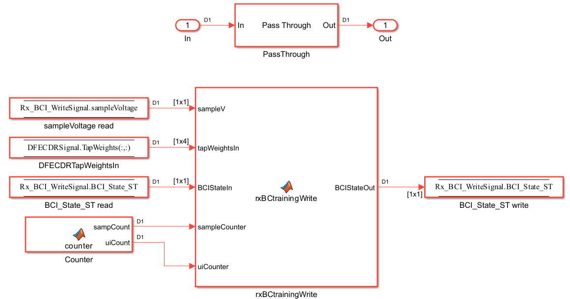
Set Up the Rx Rx_BCI_Write Block
The Rx_BCI_Write block is used at the end of each back-channel training cycle to calculate the current eye metrics and report those metrics back to the Tx_BCI block for analysis.
The first step is to set up the Rx_BCI_Write block for back-channel operation. The MATLAB Function block that controls the operation of the Rx_BCI_Write block is written later in the example.
Look under the mask in the Rx_BCI_Write block. You can see four automatically generated Data Store read/write blocks.
Delete the Data Store Write block labeled sampleVoltage write. It will not be used.
Add a Data Store Read block labeled DFECDRTapWeightsIn.
Double-click the Data Store Read block and set the Data store name to
DFECDRSignal.On the Element Selection tab, expand the signal DFECDRSignal and highlight
TapWeights[1,4].Press the Select>> button to select this element.
Save the changes.
Copy the MATLAB Function block named Counter from the Tx Tx_BCI block into this block.
Add a new MATLAB Function block and set the label to rxBCtrainingWrite. This MATLAB Function block is used to control the back-channel training process. The contents of this function will be covered later in this example. However, to complete the Rx_BCI_Write block connections you must display all the correct nodes. To enable this:
Double-click the rxBCtrainingWrite MATLAB Function block to open in the editor.
Delete all the default contents.
Insert the following function signature:
function BCIStateOut = rxBCtrainingWrite(sampleV, tapWeightsIn, BCIStateIn, sampleCounter, uiCounter, SymbolTime, SampleInterval)
The values for two of the inputs to this function, SymbolTime and SampleInterval, are inherited from the model workspace and therefore do not need to show up as nodes on the MATLAB Function block. To remove these nodes from the MATLAB Function block:
Save the model.
In the MATLAB function signature highlight the parameter SymbolTime.
Right-click the parameter and select
Data Scope for "SymbolTime".Change the Data Scope from
InputtoParameter.Repeat this process for SampleInterval.
When you save the model you should see that these two input parameters have been removed from the function block on the Simulink canvas.
Connect everything together as shown below:
Edit the txBCtraining MATLAB Function Block
The Tx_BCI block is used to control the entire back-channel training process. The first time through it initializes all the Tx and Rx parameters that will be optimized during training. After every back-channel training cycle, this block reads the current eye metric supplied by the Rx, stores this value, then updates the Tx and Rx parameters for the next pass. When training is complete this block signals the completion of training, sets all Tx and Rx parameters to their optimal values and then returns the models to regular operation.
The Tx_BCI block was set up for back-channel operation earlier in this example. Now you will create the MATLAB Function block at the heart of the Tx_BCI block. This MATLAB Function block, which was labeled txBCtraining, controls the entire back-channel training process. The steps involved in this process are as follows:
Define the function signature.
Initialize parameters and set persistent variables.
Define the parameters to be swept and their ranges.
On the first GetWave call, set up the initial starting parameter values for the Tx and the Rx.
Every back-channel training cycle read the eye metrics calculated by the Rx and decide what to do next. When training is complete signal the completion of training, output the optimal Tx and Rx parameter values to be used during simulation and write these final values to the log file.
Set the proper training state and output the FFE parameters to be used.
The following sections walk you through the code used in the txBCtraining MATLAB Function block. In the Tx block, click the Tx_BCI pass-through block and press Ctrl+U to push into the Tx_BCI pass-through block set up earlier. Double-click the txBCtraining MATLAB Function block, then Copy/Paste the code described in the following sections.
Define the Function Signature
The function signature for the txBCtraining block has 6 inputs and 2 outputs. The inputs are:
tapWeightsIn: The FFE tap weights array as defined in the FFE mask.
BCIStateIn: The back-channel state value from the TxBCIStateIn Data Store.
sampleCounter: Count of total number of samples.
uiCounter: Count of total number of UI.
SymbolTime: The UI (in seconds). This value is inherited from the Model Workspace and therefore does not need to show up as a node on the MATLAB Function block. To remove this node from the MATLAB Function block, the Data Scope was earlier set to
Parameter.SampleInterval: Simulation step size (in seconds). This value is inherited from the Model Workspace and therefore does not need to show up as a node on the MATLAB Function block. To remove this node from the MATLAB Function block, the Data Scope was earlier set to
Parameter.
There are two outputs:
tapWeightsOut: The FFE tap weights array output to the BCIFFETapWeightsOut Data Store.
BCIStateOut: The back-channel state value output to the TxBCIStateOut Data Store.
The function signature was added earlier when initially creating the MATLAB Function block and so is already present.
Initialize Parameters and Variables
This section sets up the three constants needed for calculating the size of the back-channel training cycle:
sampBit: The number of samples in each UI.
messageInterval: The length (in UI) of each back-channel training cycle. This value is currently set to ~2 PRBS7 iterations.
BCIwait: The delay time (in UI) before starting back-channel training. This value is currently set to ~4 PRBS7 iterations.
In addition to the constant values, this section sets up the 11 persistent variables used by this function. Persistent variables retain their values between each call to this MATLAB function. The 11 persistent variables are:
Protocol: The protocol being used by this back-channel model.
numDFEtaps: The number of DFE taps being included in this back-channel training algorithm.
numFFEtaps: The number FFE taps being included in this back-channel training algorithm.
DFEtaps: The current DFE tap values.
FFEtaps: The current FFE tap values.
Sequence: A integer counter used to log the sequence of training events.
State: The current back-channel training state.
EyeHeight: The current eye height (in Volts) being reported by the Rx.
step: The current training sequence step being run.
indx: An index variable for control loops.
metric: An array used to store the incoming eye heights from each training step.
To initialize these parameters and variables, Copy/Paste the following code to the bottom of the txBCtraining MATLAB Function block:
%% Setup
sampBit = round(SymbolTime/SampleInterval);  %% Calculate Samples Per Bit
messageInterval = 256;                       %% Length (in UI) of back-channel training cycle iteration (~2 PRBS7 iterations)
BCIwait = 512;                               %% Delay time (in UI) before starting training(~4 PRBS7 iterations)

%% Read BCI file to determine training values
% Make variables available between time steps
persistent Protocol numDFEtaps numFFEtaps DFEtaps FFEtaps Sequence State EyeHeight step indx metric

% Initialize variable initial conditions
if isempty(Protocol)
    Protocol = 'Defaults';
end
if isempty(numDFEtaps)
    numDFEtaps = 4;
end
if isempty(numFFEtaps)
    numFFEtaps = 3;
end
if isempty(DFEtaps)
    DFEtaps = [0.000,0.000,0.000,0.000];
end
if isempty(FFEtaps)
    FFEtaps = [0.000,1.000,0.000];
end
if isempty(Sequence)
    Sequence = 1;
end
if isempty(State)
    State = 'Testing';
end
if isempty(EyeHeight)
    EyeHeight = 0.000;
end
if isempty(step)
    step = 1;
end
if isempty(indx)
    indx = 1;
end
if isempty(metric)
    metric = zeros(50,1);
end
Define Swept Parameters
The training algorithm implemented in this example sweeps the pre and post FFE tap values and all 4 of the DFE taps individually, then selects the optimal value for each tap. Eight parameters are used to define the ranges for each of the taps and the step size to be used during training:
ffeTapStep: The step size to be used when sweeping the FFE taps. This value is negative since the FFE tap values are always <= 0.
dfeTapStep: The step size to be used when sweeping the DFE taps.
regFFEtapm1: The min/max range of values to be used when sweeping the FFE pre-tap.
regFFEtap1: The min/max range of values to be used when sweeping the FFE post-tap.
regDFEtap1: The min/max range of values to be used when sweeping the first DFE tap.
regDFEtap2: The min/max range of values to be used when sweeping the second DFE tap.
regDFEtap3: The min/max range of values to be used when sweeping the third DFE tap.
regDFEtap4: The min/max range of values to be used when sweeping the fourth DFE tap.
To define all the parameters to be swept during training, Copy/Paste the following code to the bottom of the txBCtraining MATLAB Function block:
%% Define parameter step sizes
ffeTapStep = -0.050;
dfeTapStep = 0.010;

% Map ranges to register values
regFFEtapm1 = ( 0.000:ffeTapStep:-0.300);
regFFEtap1  = ( 0.000:ffeTapStep:-0.300);
regDFEtap1  = (-0.200:dfeTapStep: 0.050);
regDFEtap2  = (-0.075:dfeTapStep: 0.075);
regDFEtap3  = (-0.060:dfeTapStep: 0.060);
regDFEtap4  = (-0.045:dfeTapStep: 0.045);
First GetWave Call
When training is enabled, the very first call to this MATLAB function needs to read the back-channel communication file written during Init to determine the full capabilities of the Tx and Rx models. This section also sets up the initial values to be used for the first back-channel training cycle. Finally, all these values are written to the back-channel communication log file.
To implement the first GetWave call, Copy/Paste the following code to the bottom of the txBCtraining MATLAB Function block:
%% First Tx GetWave Call (Sequence=3)
if sampleCounter == 1 && BCIStateIn == 2 % Training enabled
    % Read back-channel communication file to get current settings
    bciRdFile = 'BCI_comm.csv';
    [~, numDFEtaps, numFFEtaps, ~, ~, Sequence, ~, EyeHeight] = readBCIfile(bciRdFile);

    % Decide what to do first
    % Tx Params
    FFEtaps = [0.000,1.000,0.000];
    % Rx Params
    DFEtaps = [0.0000, 0.0000, 0.0000, 0.0000];

    % Write back-channel communication file with first pass settings for Rx
    bciWrFile = 'BCI_comm.csv';
    Protocol = ['DDR5' 0];   %% Null terminate string to keep fprintf happy in C++
    State = ['Training' 0];  %% Null terminate string to keep fprintf happy in C++
    Sequence = Sequence + 1;
    writeBCIfile(bciWrFile, 'w', Protocol, numel(DFEtaps), numel(FFEtaps), DFEtaps, FFEtaps, Sequence, State, EyeHeight)

    % Write to log file
    logFileName = 'BCI_comm_log.csv';
    writeBCIhistory(logFileName, 'Tx', 'GetW', sampleCounter, BCIStateIn, numel(DFEtaps), numel(FFEtaps), DFEtaps, FFEtaps, Sequence, EyeHeight)
end
Back-Channel Training Algorithm
When training is enabled, after waiting the number of UI as defined by the constant BCIwait, the back-channel training algorithm is called every training block as defined by the messageInterval constant. First the current metrics reported by the Rx are read, then those results are written to the back-channel communication log file. The training algorithm uses the following steps:
Sweep all values of the FFE pre-tap and determine which value results in the largest eye opening.
Sweep all values of the FFE post-tap and determine which value results in the largest eye opening.
Sweep all values of DFE tap 1 and determine which value results in the largest eye opening.
Sweep all values of DFE tap 2 and determine which value results in the largest eye opening.
Sweep all values of DFE tap 3 and determine which value results in the largest eye opening.
Sweep all values of DFE tap 4 and determine which value results in the largest eye opening.
When training is complete, change the State to "
Converged" and write the final values to the back-channel communication log file.
To implement the back-channel training algorithm, Copy/Paste the following code to the bottom of the txBCtraining MATLAB Function block:
%% Each subsequent BCI Block (Sequence=5,7,9,11...)
if  uiCounter > BCIwait + 2 && mod(sampleCounter - 1, (messageInterval * sampBit)) == 0 && BCIStateIn == 2 % Training enabled
    % Read setup used for previous 16 GetWaveblocks from back-channel communication file
    bciRdFile = 'BCI_comm.csv';
    [~, ~, ~, ~, ~, Sequence, ~, EyeHeight] = readBCIfile(bciRdFile);

    % Write current results to log file
    Sequence = Sequence + 1;
    logFileName = 'BCI_comm_log.csv';
    writeBCIhistory(logFileName, 'Tx', 'GetW', sampleCounter, BCIStateIn, numel(DFEtaps), numel(FFEtaps), DFEtaps, FFEtaps, Sequence, EyeHeight)
    if indx ~= 1
        % Store current metrics
        metric(indx - 1) = EyeHeight;
    end

    % Decide what to do next
    switch step
        case 1  % Step 1: Determine best value for FFE tap -1
            State = ['Training' 0];  %% Null terminate string to keep fprintf happy in C++
            if indx <= length(regFFEtapm1)
                % Set values for next iteration
                FFEtaps(1) = regFFEtapm1(indx);
                FFEtaps(3) = 0.0;
                FFEtaps(2) = 1 - abs(FFEtaps(1)) - abs(FFEtaps(3));
                indx = indx + 1;
            elseif indx == length(regFFEtapm1) + 1
                % Set best metric
                [~, jj] = max(metric);
                FFEtaps(1) = regFFEtapm1(jj);
                FFEtaps(3) = 0.0;
                FFEtaps(2) = 1 - abs(FFEtaps(1)) - abs(FFEtaps(3));

                % Done. Set up for next step
                metric = zeros(50,1);
                step = step + 1;
                indx = 1;
            end
        case 2  % Step 2: Determine best value for FFE tap 1
            State = ['Training' 0];
            if indx <= length(regFFEtap1)
                % Set values for next iteration
                %FFEtaps(1) = 0.0;   %% Use value from step 1
                FFEtaps(3) = regFFEtap1(indx);
                FFEtaps(2) = 1 - abs(FFEtaps(1)) - abs(FFEtaps(3));
                indx = indx + 1;
            elseif indx == length(regFFEtap1) + 1
                % Set best metric
                [~, jj] = max(metric);
                FFEtaps(3) = regFFEtap1(jj);
                FFEtaps(2) = 1 - abs(FFEtaps(1)) - abs(FFEtaps(3));

                % Done. Set up for next step
                metric = zeros(50,1);
                step = step + 1;
                indx = 1;
            end
        case 3  % Step 3: Determine best value for DFE tap 1
            State = ['Training' 0];
            if indx <= length(regDFEtap1)
                % Set values for next iteration
                DFEtaps = [regDFEtap1(indx), 0.0000, 0.0000, 0.0000];
                indx = indx + 1;
            elseif indx == length(regDFEtap1) + 1
                % Set best metric
                [~, jj] = max(metric);
                DFEtaps = [regDFEtap1(jj), 0.0000, 0.0000, 0.0000];

                % Done. Set up for next step
                metric = zeros(50,1);
                step = step + 1;
                indx = 1;
            end
        case 4  % Step 4: Determine best value for DFE tap 2
            State = ['Training' 0];
            if indx <= length(regDFEtap2)
                % Set values for next iteration
                DFEtaps(2:4) = [regDFEtap2(indx), 0.0000, 0.0000];
                indx = indx + 1;
            elseif indx == length(regDFEtap2) + 1
                % Set best metric
                [~, jj] = max(metric);
                DFEtaps(2:4) = [regDFEtap2(jj), 0.0000, 0.0000];

                % Done. Set up for next step
                metric = zeros(50,1);
                step = step + 1;
                indx = 1;
            end
        case 5  % Step 5: Determine best value for DFE tap 3
            State = ['Training' 0];
            if indx <= length(regDFEtap3)
                % Set values for next iteration
                DFEtaps(3:4) = [regDFEtap3(indx), 0.0000];
                indx = indx + 1;
            elseif indx == length(regDFEtap3) + 1
                % Set best metric
                [~, jj] = max(metric);
                DFEtaps(3:4) = [regDFEtap3(jj), 0.0000];

                % Done. Set up for next step
                metric = zeros(50,1);
                step = step + 1;
                indx = 1;
            end
        case 6  % Step 6: Determine best value for DFE tap 4
            State = ['Training' 0];
            if indx <= length(regDFEtap4)
                % Set values for next iteration
                DFEtaps(4) = regDFEtap4(indx);
                indx = indx + 1;
            elseif indx == length(regDFEtap4) + 1
                % Set best metric
                [~, jj] = max(metric);
                DFEtaps(4) = regDFEtap4(jj);

                % Done. Set up for next step
                metric = zeros(50,1);
                step = step + 1;
                indx = 1;
            end
        case 7  % Step 7: Training is complete
            State = ['Converged' 0];
            % Write final entry in log file
            logFileName = 'BCI_comm_log.csv';
            Sequence = Sequence + 1;
            writeBCIhistory(logFileName, 'Tx', 'GetW', sampleCounter, 3, numel(DFEtaps), numel(FFEtaps), DFEtaps, FFEtaps, Sequence, EyeHeight)
        otherwise
            State = ['Error' 0];
    end

    % Write to back-channel communication file with next pass settings for Rx
    bciWrFile = 'BCI_comm.csv';
    Protocol = ['DDR5' 0];   %% Null terminate string to keep fprintf happy in C++
    writeBCIfile(bciWrFile, 'w', Protocol, numel(DFEtaps), numel(FFEtaps), DFEtaps, FFEtaps, Sequence, State, EyeHeight)

end
Set Training State and Output Parameter Values
The last thing that needs to be done in by this MATLAB function is to update the State for the BCI_State_ST Data Store and to update the FFE tap array values.
To set the training state and output values, Copy/Paste the following code to the bottom of the txBCtraining MATLAB Function block:
%% Set back-channel state
if strcmpi(State,'Off') || strcmpi(State,['Off' 0])
    BCIStateOut = 1;
elseif strcmpi(State,'Training') || strcmpi(State,['Training' 0])
    BCIStateOut = 2;
elseif strcmpi(State,'Converged') || strcmpi(State,['Converged' 0])
    BCIStateOut = 3;
elseif strcmpi(State,'Failed') || strcmpi(State,['Failed' 0])
    BCIStateOut = 4;
else %Error
    BCIStateOut = 5;
end

%% Set output FFE values based on Training
if BCIStateOut == 2 || BCIStateOut == 3 % Training enabled/Converged
    tapWeightsOut = FFEtaps(:);
else  % Training Off/Failed/Error
    tapWeightsOut = tapWeightsIn;
end
Save and close this MATLAB Function block.
Edit the rxBCtrainingRead MATLAB Function Block
The Rx_BCI_Read block is used to read the Rx parameters values requested by the Tx_BCI block and set them for the next back-channel training cycle. If the Tx_BCI block signals that the training is complete, this block sets the final values to be used by the Rx for the remainder of the simulation.
The Rx_BCI_Read block was set up for back-channel operation earlier in this example. Now create the MATLAB Function block at the center of the Rx_BCI_Read block. This MATLAB Function block, which was labeled rxBCtrainingRead, sets the Rx DFE values to be used. The steps involved in this process are as follows:
Define the function signature.
Initialize parameters and set persistent variables.
On the first GetWave call, and at the beginning of every back-channel training cycle, read the Rx DFE tap values to be used as specified by the Tx back-channel training algorithm.
Set the proper training state and output the DFE parameters to be used.
The following sections walk you through the code used in the rxBCtrainingRead MATLAB Function block. In the Rx block, click the Rx_BCI_Read pass-through block and press Ctrl+U to push into the Rx_BCI_Read pass-through block set up earlier. Double-click the rxBCtrainingRead MATLAB Function block, then Copy/Paste the code described in the following sections.
Define the Function Signature
The function signature for the rxBCtrainingRead block has 6 inputs and 2 outputs. The inputs are:
tapWeightsIn: The DFE tap weights array as defined in the DFECDRTapWeightsIn Data Store.
BCIStateIn: The back-channel state value from the RxBCIStateIn Data Store.
sampleCounter: Count of total number of samples.
uiCounter: Count of total number of UI.
SymbolTime: The UI (in seconds). This value is inherited from the Model Workspace and therefore does not need to show up as a node on the MATLAB Function block. To remove this node from the MATLAB Function block, the Data Scope has been set to "
Parameter".SampleInterval: Simulation step size (in seconds). This value is inherited from the Model Workspace and therefore does not need to show up as a node on the MATLAB Function block. To remove this node from the MATLAB Function block, the Data Scope has been set to "
Parameter".
There are two outputs:
tapWeightsOut: The DFE tap weights array output to the DFECDRTapWeightsOut Data Store.
BCIStateOut: The back-channel state value output to the RxBCIStateOut Data Store.
The function signature was entered earlier when initially creating the MATLAB Function block and so is already present.
Initialize Parameters and Variables
This section sets up the three constants needed for calculating the size of the back-channel training cycle:
sampBit: The number of samples in each UI.
messageInterval: The length (in UI) of each back-channel training cycle. This value is currently set to ~2 PRBS7 iterations.
BCIwait: The delay time (in UI) before starting back-channel training. This value is currently set to ~4 PRBS7 iterations.
In addition to the constant values, this section sets up the 7 persistent variables used by this function. Persistent variables retain their values between each call to this MATLAB function. The 7 persistent variables are:
Protocol: The protocol being used by this back-channel model.
numDFEtaps: The number of DFE taps being included in this back-channel training algorithm.
numFFEtaps: The number FFE taps being included in this back-channel training algorithm.
DFEtaps: The current DFE tap values.
FFEtaps: The current FFE tap values.
Sequence: A integer counter used to log the sequence of training events.
State: The current back-channel training state.
To initialize the parameters and variables, Copy/Paste the following code to the bottom of the rxBCtrainingRead MATLAB Function block:
%% Setup
sampBit = round(SymbolTime/SampleInterval);  %% Calculate Samples Per Bit
messageInterval = 256;                       %% Length (in UI) of back-channel training cycle iteration (~2 PRBS7 iterations)
BCIwait = 512;                               %% Delay time (in UI) before starting training(~4 PRBS7 iterations)

% Make variables available between time steps
persistent Protocol numDFEtaps numFFEtaps DFEtaps FFEtaps Sequence State;

% Initialize variable initial conditions
if isempty(Protocol)
    Protocol = 'Defaults';
end
if isempty(numDFEtaps)
    numDFEtaps = 4;
end
if isempty(numFFEtaps)
    numFFEtaps = 3;
end
if isempty(DFEtaps)
    DFEtaps = tapWeightsIn;
end
if isempty(FFEtaps)
    FFEtaps = [0,0,0];
end
if isempty(Sequence)
    Sequence = 1;
end
if isempty(State)
    if BCIStateIn == 1     % Off
        State = ['Off' 0];
    elseif BCIStateIn == 2 % Training
        State = ['Training' 0];
    elseif BCIStateIn == 3 % Converged
        State = ['Converged' 0];
    elseif BCIStateIn == 4 % Failed
        State = ['Failed' 0];
    else  % Error
        State = ['Error' 0];
    end
end
Read DFE Tap Values to be Used
When training is enabled, on the very first call to this MATLAB function and at the beginning of every training block as defined by the messageInterval constant, the back-channel communication file is read to determine the updated DFE tap values to be used for the next training cycle.
To set up the DFE tap values to be used, Copy/Paste the following code to the bottom of the rxBCtrainingRead MATLAB Function block:
%% First GetWave block of each BCI Block (Sequence=3,5,7,9,11,...)
% Read back-channel communication file to get current settings
if  (sampleCounter == 1 && BCIStateIn == 2) || ((uiCounter > BCIwait + 2 && mod(sampleCounter - 1, (messageInterval * sampBit)) == 0) && BCIStateIn == 2) % Training enabled
    bciRdFile = 'BCI_comm.csv';
    [Protocol, numDFEtaps, numFFEtaps, DFEtaps(1,1:4), FFEtaps, Sequence, State, ~] = readBCIfile(bciRdFile);

end
Set Training State and Output Parameter Values
The last thing that needs to be done in by this MATLAB Function block is to update the State for the BCI_State_ST Data Store and to update the DFE tap array values.
To set the State and output values, Copy/Paste the following code to the bottom of the rxBCtrainingRead MATLAB Function block:
%% Set back-channel state
if strcmpi(State,'Off') || strcmpi(State,['Off' 0])
    BCIStateOut = 1;
elseif strcmpi(State,'Training') || strcmpi(State,['Training' 0])
    BCIStateOut = 2;
elseif strcmpi(State,'Converged') || strcmpi(State,['Converged' 0])
    BCIStateOut = 3;
elseif strcmpi(State,'Failed') || strcmpi(State,['Failed' 0])
    BCIStateOut = 4;
else %Error
    BCIStateOut = 5;
end

%% Set output DFE values based on Training
if BCIStateOut == 2 % Training enabled
    tapWeightsOut = DFEtaps(1,1:4);
else
    tapWeightsOut = tapWeightsIn;
end
Save and close this MATLAB Function block.
Edit the rxBCtrainingWrite MATLAB Function Block
The Rx_BCI_Write block is used at the end of each back-channel training cycle to calculate the current eye metrics and report those metrics back to the Tx_BCI block for analysis.
The Rx_BCI_Write block was set up for back-channel operation earlier in this example. Now the MATLAB Function block at the center of the Rx_BCI_Write block will be created. This MATLAB Function block, which we labeled rxBCtrainingWrite, will calculate the minimum eye height of the last 127 bits and write those values to the back-channel communication file and log file. The steps involved in this process are as follows:
Define the function signature.
Initialize parameters and set persistent variables.
Store a vector of voltages to be used when calculating the minimum eye height.
At the end of each back-channel training cycle calculate the minimum eye height and write it to the back-channel communication file.
Update the training state.
The following sections will walk through the code used in the rxBCtrainingWrite MATLAB Function block. In the Rx block, click the Rx_BCI_Write pass-through block and press Ctrl+U to push into the Rx_BCI_Write pass-through block set up earlier. Double-click the rxBCtrainingWrite MATLAB Function block, then Copy/Paste the code described in the following sections.
Define the Function Signature
The function signature for the rxBCtrainingWrite block has 7 inputs and 1 output. The inputs are:
sampleV: The voltage at the CDR sample time.
tapWeightsIn: The DFE tap weights array as defined in the DFECDRTapWeightsIn Data Store.
BCIStateIn: The back-channel state value from the RxBCIStateIn Data Store.
sampleCounter: Count of total number of samples.
uiCounter: Count of total number of UI.
SymbolTime: The UI (in seconds). This value is inherited from the Model Workspace and therefore does not need to show up as a node on the MATLAB Function block. To remove this node from the MATLAB Function block, the Data Scope has been set to "
Parameter".SampleInterval: Simulation step size (in seconds). This value is inherited from the Model Workspace and therefore does not need to show up as a node on the MATLAB Function block. To remove this node from the MATLAB Function block, the Data Scope has been set to "
Parameter".
There is one output:
BCIStateOut: The back-channel state value output to the RxBCIStateOut Data Store.
The function signature was entered earlier when initially creating the MATLAB Function block and so is already present.
Initialize Parameters and Variables
This section sets up the four constants needed for calculating the size of the back-channel training cycle:
sampBit: The number of samples in each UI.
messageInterval: The length (in UI) of each back-channel training cycle. This value is currently set to ~2 PRBS7 iterations.
BCIwait: The delay time (in UI) before starting back-channel training. This value is currently set to ~4 PRBS7 iterations.
windowLength: The length of the window (in UI) used to calculate the minimum eye height. This value is currently set to 1 PRBS7 iteration.
In addition to the constant values, this section sets up the 5 persistent variables used by this function. Persistent variables retain their values between each call to this MATLAB function. The 5 persistent variables are:
Protocol: The protocol being used by this back-channel model.
Sequence: A integer counter used to log the sequence of training events.
State: The current back-channel training state.
EyeHeight: The calculated inner eye height value (in Volts).
vSamp: The sample voltage being reported by the CDR block.
To initialize all parameters and variables for this block, copy and paste the following code to the bottom of the rxBCtrainingWrite MATLAB Function block:
%% Setup
sampBit = round(SymbolTime/SampleInterval);  %% Calculate Samples Per Bit
messageInterval = 256;                       %% Length (in UI) of back-channel training cycle iteration (~2 PRBS7 iterations)
BCIwait = 512;                               %% Delay time (in UI) before starting training(~4 PRBS7 iterations)
windowLength = 127;                          %% Length of window (in UI) used to calculate minimum eye height (1 PRBS7 iteration)

% Make variables available between time steps
persistent Protocol Sequence State EyeHeight vSamp

if isempty(State)
    if BCIStateIn == 1     % Off
        State = ['Off' 0];
    elseif BCIStateIn == 2 % Training
        State = ['Training' 0];
    elseif BCIStateIn == 3 % Converged
        State = ['Converged' 0];
    elseif BCIStateIn == 4 % Failed
        State = ['Failed' 0];
    else  % Error
        State = ['Error' 0];
    end
end
Store Vector of Reported Voltages
This section accumulates a rolling vector of voltages to be used in the minimum eye height calculation. We will assume that these voltages are symmetric around 0V, so the absolute value is used.
To store the report eye voltage values, Copy/Paste the following code to the bottom of the rxBCtrainingWrite MATLAB Function block:
%% Accumulate rolling vector of voltages for minimum eye height calculations
if isempty(vSamp)
    vSamp = zeros(1, windowLength * sampBit);
end
vSamp = circshift(vSamp, 1);
vSamp(1) = abs(sampleV);      % Assume symmetry and only use positive values
Calculate Minimum Eye Height and Write to File
When training is enabled, after waiting the number of UI as defined by the constant BCIwait the back-channel metrics are calculated at the end of each training iteration as defined by the messageInterval constant. First the back-channel configuration is read from the back-channel communication file, then the inner eye height value is calculated and the results output to the back-channel communication file and the log file.
To calculate the eye metrics and write to the communication file every back-channel cycle, Copy/Paste the following code to the bottom of the rxBCtrainingWrite MATLAB Function block:
%% Write current state and eye metrics at the end of each BCI block
if  uiCounter > BCIwait + 2 && mod(sampleCounter, (messageInterval * sampBit)) == 0 && BCIStateIn == 2 % Training enabled  (Sequence=4,6,8,10,12,...)

    % Read setup used for last 16 GetWaveblocks from back-channel communication file
    bciRdFile = 'BCI_comm.csv';
    [Protocol, ~, ~, ~, FFEtaps, Sequence, State, ~] = readBCIfile(bciRdFile);

    % Calculate inner eye height from sampled voltage:
    EyeHeight = min(vSamp) * 2;    % 2x since using absolute value.

    % Write new back-channel communication file with end of BCI-Block metrics
    bciWrFile = 'BCI_comm.csv';
    Sequence = Sequence + 1;
    writeBCIfile(bciWrFile, 'w', Protocol, numel(tapWeightsIn), numel(FFEtaps), tapWeightsIn, FFEtaps, Sequence, State, EyeHeight)
    %
    % Write to log file:
    logFileName = 'BCI_comm_log.csv';
    writeBCIhistory(logFileName, 'Rx', 'GetW', sampleCounter, BCIStateIn, numel(tapWeightsIn), numel(FFEtaps), tapWeightsIn, FFEtaps, Sequence, EyeHeight)

end
Set the Training State
The last thing that needs to be done in this MATLAB Function block is to update the State for the BCI_State_ST Data Store.
To set the training state, Copy/Paste the following code to the bottom of the rxBCtrainingRead MATLAB Function block:
%% Update State Out if State In changed
if BCIStateIn == 3     % Converged
    State = ['Converged' 0];
elseif BCIStateIn == 4 % Failed
    State = ['Failed' 0];
end

if strcmpi(State,'Off') || strcmpi(State,['Off' 0])
    BCIStateOut = 1;
elseif strcmpi(State,'Training') || strcmpi(State,['Training' 0])
    BCIStateOut = 2;
elseif strcmpi(State,'Converged') || strcmpi(State,['Converged' 0])
    BCIStateOut = 3;
elseif strcmpi(State,'Failed') || strcmpi(State,['Failed' 0])
    BCIStateOut = 4;
else %Error
    BCIStateOut = 5;
end
Save and close this MATLAB Function block.
In Simulink, press Ctrl+D to compile the model and check for errors. Resolve any errors before proceeding.
Note: A common error is to incorrectly connect data stores to the MATLAB Function blocks. If you have any errors, review all connections in each of the pass-through blocks.
Run the Model and Verify Results
The next step is to run the model and verify that the back-channel code is operating correctly.
Set Up Simulation Parameters
Before running the complete model, open the Stimulus block to set the stimulus pattern used to test the model:
Set the Number of symbols to
50000to allow the back-channel training algorithm enough time to complete.Set the Waveform creation method to
Serial PRBS.Set PRBS order to
7, so that a PRBS7 pattern will be used during simulation.
Next, open the IBIS-AMI Manager. On the Export tab, set the Rx Bits to ignore to 25000 to allow time for the back-channel algorithm to complete before starting to save the output waveform.

Test Proper Operation of Tx and Rx Models
Run the model. While the model is running, observe the time domain waveform changing as each of the tap settings is swept. When the simulation is complete the back-channel communication file, BCI_comm.csv, now contains the final optimized FFE and DFE tap settings and should look something like:
Protocol,DDR5,
numDFEtaps,4,
numFFEtaps,3,
DFEtaps,0.00000,-0.00500,-0.00000,-0.00500,
FFEtaps,0.00000,0.85000,-0.15000,
Sequence,176,
State,Converged,
EyeHeight,0.543841,
Open the back-channel communication log file, BCI_comm_log.csv, in a spreadsheet editor. Each row in the log file shows the Sequence number, which model wrote to the file (Tx or Rx), the current Sample Count, BCI_State and calculated Eye Height. The last 7 columns in the log show the current FFE and DFE taps values being simulated. Observe how the Eye Height changes as each value is swept, and the parameter value that gives the largest Eye Height is set after each iteration. Note that the value of FFE0 is always computed from the values of FFE-1 and FFE1.
Generate DDR5 Tx/Rx IBIS-AMI Model
The final part of this example takes the customized Simulink model and generates IBIS-AMI compliant DDR5 model executables, IBIS and AMI files.
Open the SerDes IBIS-AMI Manager.
Export Models
On the Export tab in the SerDes IBIS-AMI Manager dialog box:
Update the Tx model name to
ddr5_bc_tx.Update the Rx model name to
ddr5_bc_rx.Note that the Tx and Rx corner percentage is set to
10. This will scale the min/max analog model corner values by +/-10%.Verify that Dual model is selected for both the Tx and the Rx AMI Model Settings. This will create model executables that support both statistical (Init) and time domain (GetWave) analysis.
Set the Tx model Bits to ignore value to
3since there are three taps in the Tx FFE.Set the Rx model Bits to ignore value to 25
000to allow enough time for training to complete during time domain simulations.Set Models to export as Both Tx and Rx so that all the files are selected to be generated (IBIS file, AMI files and DLL files).
Set the IBIS file name to be
ddr5_bc_txrx.ibsJitter can be added if desired on the AMI-Tx and AMI-Rx tabs.
Press the Export button to generate models in the Target directory.
Update AMI Files (If Desired)
The Tx and Rx AMI files generated by SerDes Toolbox are compliant to the IBIS 6.1 specification, so all back-channel specific parameters have been placed in the Model_Specific section of the file.
The BCI_State_ST parameter has 5 states required for complete back-channel training, however to make these models more user-friendly the end user only really needs 2 states: "Off" and "Training". To make this change, update the BCI_State_ST parameter in each AMI file as follows:
Change (List 1 2 3 4 5) to
(List 1 2).Change (List_Tip "Off" "Training" "Converged" "Failed" "Error") to
(List_Tip "Off" "Training").Note that this will not affect the operation of the model, only the parameter values visible to the user.
Test Generated IBIS-AMI Models
The DDR5 transmitter and receiver IBIS-AMI models are now complete and ready to be tested in any industry standard AMI model simulator.
Model Limitations
When simulating with these models in an industry standard AMI model simulator, keep the following limitations in mind:
It is intended that these models will be run as a "matched set" or with other back-channel AMI models that have been generated using SerDes Toolbox.
These models will not work with AMI models generated outside of SerDes Toolbox. Specifically, any model that uses the IBIS standard BCI_* keywords.
BCI_Protocol is not supported. These models have been hard coded to a Protocol named "DDRx_Write".
BCI_ID is not supported. These models have been hard coded to a BCI_ID named "bci_comm", which means that each simulation must be run in a separate directory to avoid filename collisions during simulation.
Back-channel training must be enabled on both models for training to be enabled. This is done by setting the BCI_State_ST parameters to "Training".
These models must be run with a block size of 1024 for proper operation.
These models will operate correctly with any UI or Samples Per Bit values.
References
[1] IBIS 7.0 Specification, https://ibis.org/ver7.0/ver7_0.pdf.
[2] JEDEC website, https://www.jedec.org/.
See Also
FFE | PassThrough | VGA | DFECDR | SerDes Designer