Pre-Layout Analysis of Serial Link
Pre-layout analysis provides you with an integrated signal integrity, timing and crosstalk analysis environment to determine system-level noise and timing margins. The pre-layout analysis environment is used to generate design guidelines for your board layouts, package layouts, connectors and cabling. From the Pre-layout tab, you may perform simple or complex solution space analysis by varying elements, such as: topology, termination, voltage, temperature, process (silicon and etch), models, UIs, corner conditions, populations, and coupling.
A schematic represents an uncoupled net or a coupled net. Uncoupled nets can be thought of as net classes. The Serial Link Designer app stores this information as a Transfer Net, which is used as the underlying data structure for all of the analysis. The Transfer Net data can be re-used in post-layout and other projects.
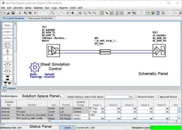
The Pre-Layout Analysis tab consists of three major panels:
Schematic Panel —This is where you graphically create and edit the circuit schematic. You can also define the data from the sheet simulation control settings.
Solution Space Panel — This is where you enter your solution space values for performing parameter sweeps.
Status Panel — This panel displays the simulation counts and schematic set information.
Double clicking a symbol on a schematic sheet launches an Element Properties dialog box for that symbol type. Each symbol type has a unique set of properties that are set from the Element Properties dialog box. If the properties are parameters that can be swept, that is also controlled from the Element Properties dialog box.
Schematic Elements
Designator — The I/O buffer is represented by a designator in the schematic. A schematic must have at least one designator that can be a driver. The buffers can be single-ended or differential. Buffer symbols has a default I/O buffer model after being placed on the schematic. You can change the buffer model for a designator in three different ways: from the Edit Designator Properties dialog, from the Select IBIS File & Model dialog, and from the default model menu items. IBIS files must be imported into the libraries before they can be used. HSPICE models must be wrapped and put in the libraries before they can be used.
Transmission Line — There are two types of transmission lines: ideal transmission lines and lossy transmission lines. Ideal transmission line models have two parameters: Impedance (Z0) and delay (Tpd). Lossy transmission lines have a frequency dependent RLGC model that is created by a 2-D field solver. Lossy transmission lines can be single-ended or differential..
Via — You can create via models based on a stackup and via physical parameters. Via models can be single-ended or differential. The first time a via symbol is placed on a sheet the default stackup is created. A dialog launches to allow the number of signal layers in the default stackup to be specified.
S-Parameters — You must import the S-Parameter files into the Serial Link Designer app before you can use them in schematic sheet. After a symbol has been placed on a schematic, the port map can be edited by right clicking on the symbol and selecting Edit Port Map from the menu.
Passive Subcircuits — You must manually import the SPICE subcircuit models for passive elements in the Serial Link Designer app libraries before you can place them on the schematic.
Probe — Voltage probe can be single-ended or differential. When a probe symbol is placed on a schematic it automatically creates a waveform node in the waveform file at the probed location. The waveform at the node can be viewed in the SI Viewer app.
Solution Space
The Solution Space panel is used to create parameter sweeps. There are variables that are always part of the solution space. Other variables in the table are created when parameters are set to be swept. The values can be typed into fields, lists or range/steps depending on the variable type.
The solution space panel can be in one of two modes:
Permutation mode — Each row is treated as an independent variable unless they are in the same variation group. The number of simulations represented by the solution space is all of the combinations of all of the variable values.
Case mode — Each column represents a simulation case. The number of simulations represented by the solution space is the number of columns.
Sheet Simulation Control
You can specify the specify the simulation state, unit interval (UI), topology, transfer net type, AC noise type, and the number of aggressors for SSO/coupled mode analysis of each schematic sheet using the sheet simulation control symbol.