Build a Shared Communication Channel with Multiple Senders and Receivers
This example shows how to model communication through a shared channel with multiple senders and receivers by using Simulink® messages, SimEvents®, and Stateflow®.
For an overview about messages, see Simulink Messages Overview.
In this model, there are two software components that send messages and two components that receive messages. The shared channel transmits messages with an added delay. SimEvents blocks are used to create custom communication behavior by merging the message lines, and copying and delaying messages. A Stateflow chart is used in a send component to send messages based on a decision logic.

Create Components to Send Messages
In the model, there are two software components that output messages, Send and StateflowSend.
In the Send component, the Sine Wave block is the signal source. The block generates a sine wave signal with an amplitude of 1. The sample time for the block is 0.1. The Send block converts the signal to a message that carries the signal value as data. The Send component sends messages to Send Buffer 1.

In the StateflowSend component, another Sine Wave block generates a sine wave signal and a Noise block injects noise into the signal. The Noise block outputs a signal whose values are generated from a Gaussian distribution with mean of 0 and variance of 1. The sample time of the block is 0.1.
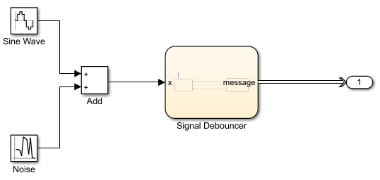
The Stateflow chart represents a simple logic that filters the signal and decides whether to send messages. If the value of the signal is greater than 0.5 for a duration greater than 0.1, then the chart sends a message that carries the signal value. If the signal value is below 0, then the chart transitions to the ReceiveSignal state. The StateflowSend component sends messages to Send Buffer 2.

For more information about creating message interfaces, see Establish Message Send and Receive Interfaces Between Software Components.
Create Components to Receive Messages
In the model, there are two software components that receive messages, Receive and Listener.
In the Receive component, a Receive block receives messages and converts the message data to signal values.

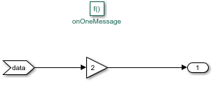
In the Listener component, there is a Simulink Function block. The block displays the function, onOneMessage(data), on the block face.

When a message arrives at Receive Buffer 2, the Listener block is notified and it takes the argument data, which is the value from the message data, as the input signal. In the block, data values are multiplied by 2. The block outputs the new data value.
Routing Messages Using SimEvents
In the shared channel, the message paths originating from the two message-sending components are merged to represent a shared communication channel.

A SimEvents Entity Input Switch block merges the message lines. In the block:
Number of input ports specifies the number of message lines to be merged. The parameter value is
2for two message paths.
Active port selection specifies how to select the active port for message departure. If you select
All, all of the messages arriving at the block are able to depart the block from the output port. If you selectSwitch, you can specify the logic that selects the active port for message departure. For this example, the parameter is set toAll.
A SimEvents Entity Server block is used to represent message transmission delay in the shared channel. In the block:
Capacity is set to
1, which specifies how many messages can be processed at a time.
Service time value is set to
1, which specifies how long it takes to process a message
A SimEvents Entity Replicator block is used to generate identical copies of messages. In the block:
Replicas depart from specifies if the copies leave the block from separate output ports or the same output port as the original messages. The parameter is set to
Separate output ports.
Number of replicas is set to
1, which specifies the number of copies generated for each message.
Hold original entity until all replicas depart holds the original message in the block until all of its copies depart the block.
A SimEvents Entity Terminator block is used to model Receive Buffer 2. In the block:
Under the Event actions tab, in the Entry action field, you can specify MATLAB® code that performs calculations or Simulink function calls that are invoked when the message enters the block. In this example,
onOneMessage(entity)is used to notify the Simulink Function block in the Listener component. To visualize the function call, under Debug tab, select Information Overlays and then Function Connectors.

Simulate the Model and Review Results
Simulate the model. Observe that the animation highlights the messages flowing through the model. You can turn off the animation by right-clicking on the model canvas and setting Animation Speed to None.

When you pause the animation, a magnifying glass appears on the blocks that store messages. If you point to the magnifying glass, you see the number of messages stored in the block.
To observe which messages are stored in the block, click the magnifying glass to open the Storage Inspector. For instance, the graphic below illustrates the messages stored in Send Buffer 1.

Turn the animation off and open the Sequence Viewer block to observe the Simulink Function calls and the flow of messages in the model.
For instance, observe the simulation time 0, during which a message carrying value 0 is sent from the Send component to Send Buffer 1. From simulation time 0.1 to 0.5, the Send component keeps sending messages to Send Buffer 1 with different data values. At time 0.5, the StateflowSend component sends a message to Send Buffer 2. For more information about using the Sequence Viewer block, see Use the Sequence Viewer to Visualize Messages, Events, and Entities.

Select a Web Site
Choose a web site to get translated content where available and see local events and offers. Based on your location, we recommend that you select: United States.
You can also select a web site from the following list
Americas
- América Latina (Español)
- Canada (English)
- United States (English)
Europe
- Belgium (English)
- Denmark (English)
- Deutschland (Deutsch)
- España (Español)
- Finland (English)
- France (Français)
- Ireland (English)
- Italia (Italiano)
- Luxembourg (English)
- Netherlands (English)
- Norway (English)
- Österreich (Deutsch)
- Portugal (English)
- Sweden (English)
- Switzerland
- United Kingdom (English)
Asia Pacific
- Australia (English)
- India (English)
- New Zealand (English)
- 中国
- 日本Japanese (日本語)
- 한국Korean (한국어)