Air Traffic Control Radar Design
This example shows how to model a conceptual air traffic control (ATC) radar simulation based on the radar range equation.
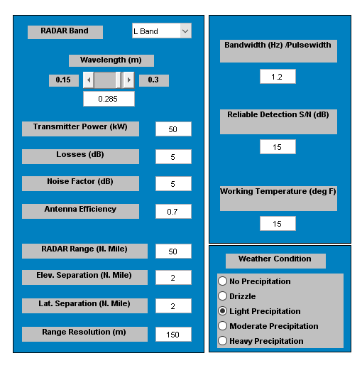
Model Description
To make parameters for Radar System Design easier to change and easier to determine their values, the model has a GUI. Radar and weather parameters may be changed from this GUI. While simulating, the effects of these parameters can be seen on the scope display which shows the actual aircraft range in yellow and the estimated aircraft range from the radar in magenta. Another output that can be viewed is the calculated signal to noise ratio (SNR) is compared to the ideal SNR. Ideal SNR is also specified from the GUI. The result is shown in the display block and will be either 1 (SNR >= ideal SNR) or 0 (SNR < ideal SNR).
Simulink® and Stateflow® are used in the model, which is divided into three main subsystems, radar, aircraft, and weather.
Using subsystems is helpful in two ways: the model is organized and easier to understand and the work can be split between multiple engineers by subsystems. The Stateflow machine labeled "check SNR" performs the logic comparing calculated SNR to the ideal SNR and output data based on this comparison.
You can run the simulation to determine if the radar can pick up the aircraft by the output on the scope. Using the GUI, the radar and the weather parameters can be altered and will change the range where the aircraft can be "seen".
Open and simulate the aero_atc model.
open_system('aero_atc');

sim('aero_atc');
Design Issues
Radar systems are designed for a specific purpose and can very seldom be used for other applications effectively. Each new radar specification requires the computation of new parameter values. When designing a radar for an application, there are a number of parameters which shape the design. Some of these parameters are contained or derived logically from the customer specification. Others are selected arbitrarily using the design engineer's best judgment. This is the first approximate solution for the system design. From here, continual refinement of the design parameters takes place until an optimum design is reached. If any changes occur in the customer specification, it could cause a need to rework the design process over from the beginning. The parametric nature of this design strategy lends itself to automation.
Design Specification
We're interested in performing conceptual design for a ground-based air traffic control (ATC) radar. Let's take a look at a potential customer specification.
This is an example of a customer specification upon which a design process would be based. The customer, possibly the FAA, provides some basic requirements for the radar design leaving a number of parameter selections up to the design engineer.
It should be noted that some of the logically derived parameters depend on assumptions made by the engineer and would need to be recalculated each time the best-judgment parameters are optimized. This problem lends itself well to simulation. By using Simulink and Stateflow, the design engineer has the analysis capability to have time-varying design cases for Monte Carlo test runs, i.e.: aircraft cross-sections and locations, weather cross-sections, and locations.
MathWorks Products in the Design Process
Here's how MathWorks® products fit the job of conceptual radar design:

Using the customer specification and the radar range equations along with equations describing the physics of the system, a model is built in MATLAB®, Simulink, and Stateflow. Using the model with the sim command for batch runs, those best-judgment parameters can be optimized for various conditions, weather, aircraft, using a Monte Carlo simulation run to prove robustness. The result is a set of optimized radar parameters that can be used to build a detailed block diagram model of the full radar system for further system analysis in Simulink with the DSP System Toolbox™.
See Also
Topics
- Aerospace Blockset
- Create Aerospace Models (Aerospace Blockset)