Control a Simulink Simulation with App Designer
This example shows how to create an interface to control a simulation for a Simulink® model. The app demonstrates connecting UI components to model elements with bindings and callbacks. This example shows how you can use an app as a user interface to load inputs for simulating a model, and save the simulation output.
Open the Model
This example uses a model of a mass-spring-damper. The Simulink model uses signal connections that define how data flows from one block to another.
open_system("ex_mass_spring_damper_appdemo")Open and Examine the App
Open the controlSimulations.mlapp in App Designer. The app provides a user interface to interact with the ex_mass_spring_damper_appdemo model. You can run the model, view the elapsed time, change the model stop time, and tune a model variable from within the app. The app contains Simulink UI components and common App Designer components. You can connect components with certain variables and signals in the Simulink model. Connecting the signals and variables in the model with the UI components allows you to visualize the signal and control the values for the simulation from your app.
open("controlSimulations.mlapp")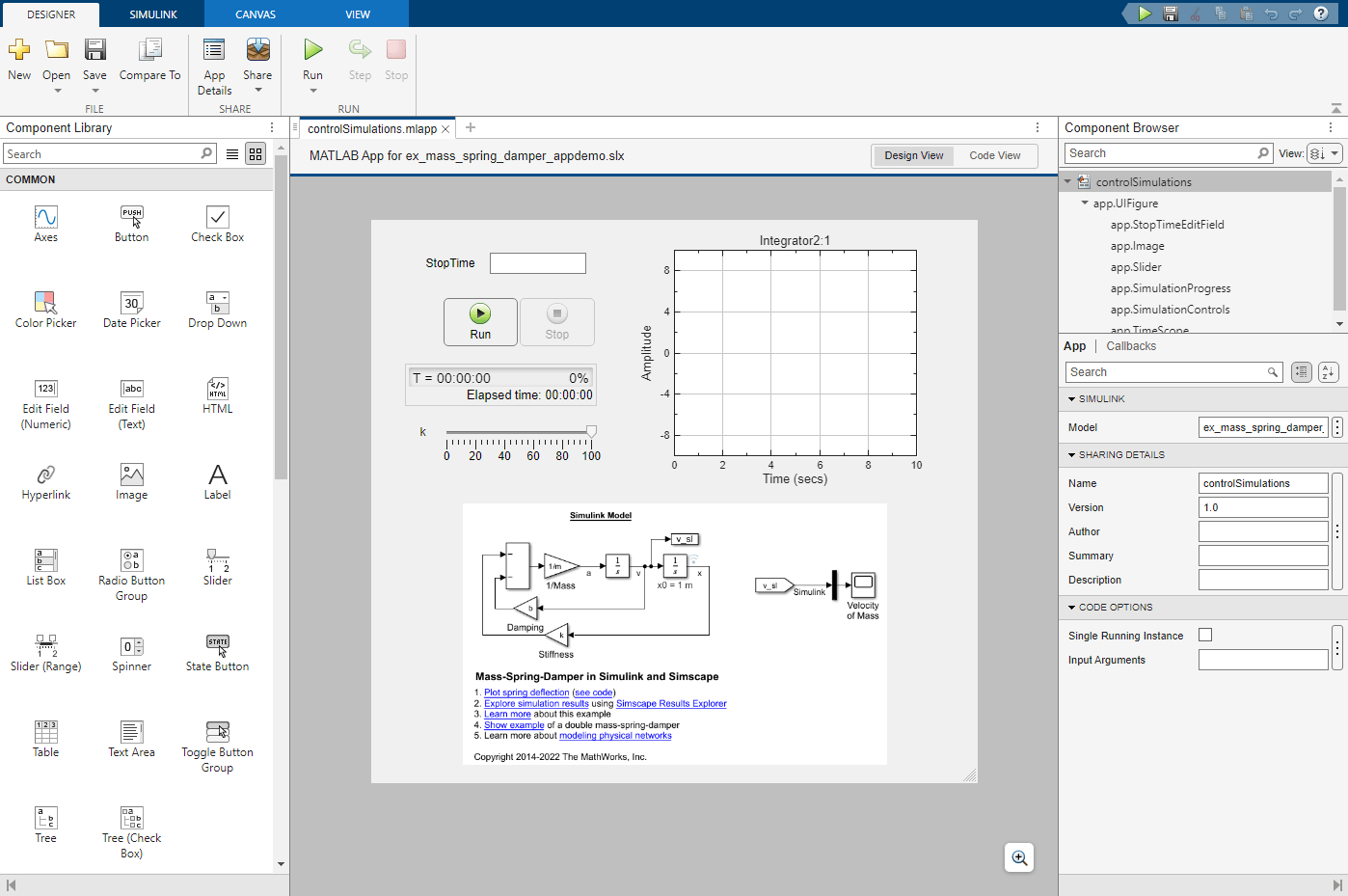
The controlSimulations app contains the following UI components:
Simulation Controls (Simulink section) — Start, pause, and stop the simulation of the model.
Simulation Progress (Simulink section) — Monitor the progress of the simulation, as well as simulation time, and elapsed time.
Time Scope (Simulink section) — Display time domain signals in the app. You can connect this UI component with a logged signal in the Simulink model.
Edit Field (Common section) — Specify simulation stop time.
Slider (Common section) — Specify a value for a tunable variable that it is connected with. You can also specify the range of values.
Image (Common section) — Display a model image.
Control Simulations Using UI Components
Connect these the UI components in the app to elements of the model:
Connect the time scope to the velocity signal named
v, which is the output signal of an Integrator block, by creating a binding.Connect the slider to the stiffness variable named
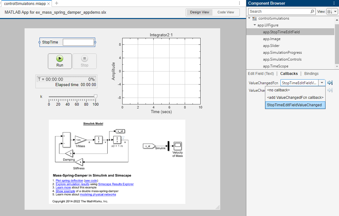
kby creating a binding.Connect the edit field to the simulation stop time by creating a callback that updates the
StopTimemodel parameter of theSimulationobject.
To learn how to bind UI components to elements, see Connect UI Components to Simulink Model Elements.
The StopTime edit field is not a Simulink UI component. It is a standard UI component that is configured programmatically to set the StopTime model parameter. You can programmatically configure the simulation object by using the Simulation app property. The StopTime edit field is attached to the model parameter StopTime using a callback function. Select the StopTime edit field in App Designer. To see the callbacks for the StopTime edit field, click Callbacks. To examine this function, switch to Code View. In Code View, you can see the callback function StopTimeEditFieldValueChanged.
function StopTimeEditFieldValueChanged(app,event)
    value = app.StopTimeEditField.Value;
    app.Simulation.setModelParameter("StopTime",num2str(value));
end
Run the App
Once you modify the app and bind the UI components to the model elements, you can run the app. To open the app, on the toolstrip, click Run.

To simulate the model from the app, click Run. The app displays the velocity signal v for the selected stiffness value k. To observe how the different values of stiffness affects the velocity signal, change the value of the variable k and run the simulation again.
Load Inputs
Once you have the app running, you can load different sets of external inputs for the simulation. To load the variables for the simulation, click Load Input. Then, select the Force.mat file. The filename appears under the Load Input button.
Interact with Tunable Variables
To start the simulation, click Run.
Save Simulation Output
Once the simulation is complete, to save simulation outputs to a MAT file, click Save Output.