Import RoadRunner Scene into Unreal Engine Using Simulink
This example shows how to import a scene built in RoadRunner into Unreal Engine® simulation environment using Simulink®. The example also shows how to generate vision detections, ground-truth semantic segmentation labels, and depth data during simulation.
You can import a RoadRunner scene using the Simulation 3D Scene Configuration block. You can use the simulation data from this example with other sensor data to develop and validate an algorithm for automated driving.
Open Model
Open the Simulink model.
open_system("RoadRunnerSceneImport");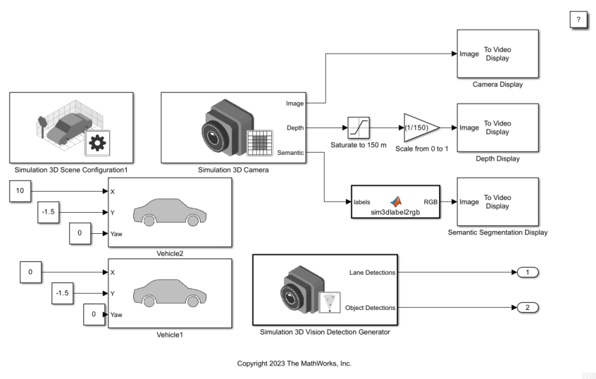
Explore Model
The model simulates two vehicles in a RoadRunner scene. The model includes a Simulation 3D Scene Configuration block, two Simulation 3D Vehicle with Ground Following blocks, a Simulation 3D Camera block, and a Simulation 3D Vision Detection Generator block.
The Simulation 3D Scene Configuration block implements the 3D simulation environment. For this example, this block imports a RoadRunner scene for simulation.
When you export a RoadRunner scene as described in Export to Unreal Using Filmbox (.fbx) File (RoadRunner), three files are available in a folder:
Filmbox (
.fbx) fileXML (
.rrdata.xml) fileASAM OpenDrive (
.xodr) file
To open the Block Parameters dialog box, double-click block. To import the RoadRunner scene, Scene source is set to RoadRunner, and Project specifies the Filmbox (.fbx) file.

The Simulation 3D Vehicle with Ground Following (Automated Driving Toolbox) block implements two vehicles, Vehicle1 and Vehicle2, in the scene. The inputs X, Y, and Yaw have constant values to position Vehicle1 behind Vehicle2.
The Simulation 3D Camera (Automated Driving Toolbox) block mounted at a location relative to Vehicle1 outputs the images captured during the simulation. To open the Block Parameters dialog box, double-click block. To specify the mounting location, in the Mounting tab, select the Mounting location as Origin. Select the Specify offset check box to set the Relative translation and Relative rotation of the camera.

In the Ground Truth tab, select Output depth and Output semantic segmentation for depth and semantic segmentation data. This block uses the XML (.rrdata.xml) file to apply labels (semantic type) to the RoadRunner Scene during import. The block outputs the camera, depth, and semantic segmentation displays by using To Video Display (Computer Vision Toolbox) blocks.
The Simulation 3D Vision Detection Generator (Automated Driving Toolbox) block generates lane and object detections by a vision sensor mounted on the rearview mirror of Vehicle1. This block uses the ASAM OpenDrive (.xodr) file for lane detection data.
Explore Simulation Data
Before you simulate the model, view the data for depth, semantic segmentation, and vision detection.
Depth Data
A depth map is a grayscale representation of camera sensor output. These maps visualize camera images in grayscale, with brighter pixels indicating objects that are farther away from the sensor. You can use depth maps to validate depth estimation algorithms for your sensors.
The Depth port of the Simulation 3D Camera block outputs a depth map of values in the range of 0 to 1000 meters. In this model, for increased visibility, a Saturation block saturates the depth output to a maximum of 150 meters. Then, a Gain block scales the depth map to the range [0, 1] so that the To Video Display block can visualize the depth map in grayscale.
Semantic Segmentation Data
Semantic segmentation describes the process of associating each pixel of an image with a class label, such as road, building, or traffic sign. The 3D simulation environment, generates synthetic semantic segmentation data according to a label classification scheme. You can use these labels to train a neural network for automated driving applications, such as road segmentation. By visualizing the semantic segmentation data, you can verify your classification scheme.
The Semantic port of the Simulation 3D Camera block outputs a set of labels for each pixel in the output camera image using the XML (.rrdata.xml). Each label corresponds to an object class. For example, in the default classification scheme used by the block, the label 1 corresponds to buildings. The label 0 refers to objects of an unknown class and appears black. For a complete list of label IDs and their corresponding object descriptions, see Labels (Automated Driving Toolbox).
The MATLAB Function block uses the label2rgb (Image Processing Toolbox) function to convert the labels to a matrix of RGB triplets for visualization. The colors are mapped to the predefined label IDs used in the default 3D simulation scenes. The helper function sim3dColormap defines the colormap.
Vision Detection Data
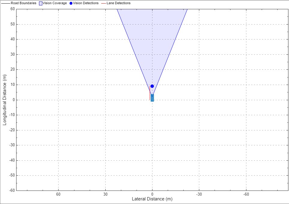
Vision detections can be used to model or simulate driving scenarios. For vision detection data, you can use the Bird's-Eye Scope (Automated Driving Toolbox) to view the coverage area of vision sensor, object detections, and lane detections from the vision sensor. The Object Detections port shows any objects in the vision coverage area. The Lane Detections port detects the lane using the imported ASAM OpenDrive (.xodr) file.
To view the vision detection, set up the Bird's-Eye Scope before you start the simulation. The Bird's-Eye Scope is a model-level visualization tool that you can open from the Simulink toolstrip. On the Simulation tab, under Review Results, click Bird's-Eye Scope. After opening the scope, click Find Signals to set up the signals. Then, run the simulation to display the vehicle, vision detection, and lane detections.
Simulate Model
Simulate the model to view the imported RoadRunner scene with two vehicles in the Simulation 3D Viewer window. When the simulation starts, the Simulation 3D Viewer window displays the RoadRunner scene with two vehicles.

Behind the Simulation 3D Viewer window, you can view displays for camera, depth, semantic segmentation, and vision detection.
Camera Display
The Image port of the Simulation 3D Camera block outputs a 3D camera image of the simulation.

Depth Display

Semantic Segmentation Display

Vision Detection Display
See Also
Simulation 3D Scene Configuration