Tune Field-Oriented Controllers for an Asynchronous Machine Using Closed-Loop PID Autotuner Block
This example shows how to use the Closed-Loop PID Autotuner block to tune Field-Oriented Control (FOC) for an asynchronous machine (ASM) in just one simulation.
Introduction of Field-Oriented Control
In this example, field-oriented control (FOC) for an asynchronous machine (ASM) is modeled in Simulink® using Simscape™ Electrical™ components. The model is based on the Simscape example Three-Phase Asynchronous Drive with Sensor Control (Simscape Electrical).
mdl = 'scdfocasmPIDTuning';
open_system(mdl)
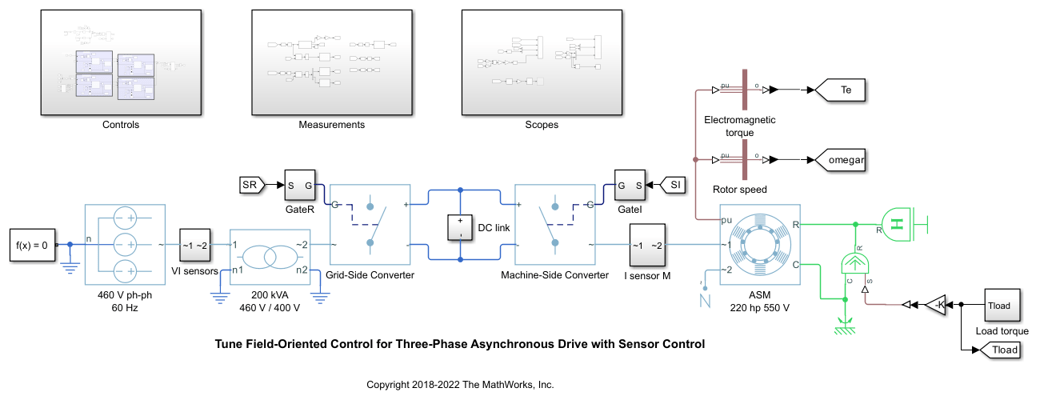
Field-oriented control controls 3-phase stator currents as a vector. FOC is based on projections, which transform a 3-phase time-dependent and speed-dependent system into a two coordinate time-invariant system. These transformations are the Clarke Transformation, Park Transformation, and their respective inverse transforms. These transformations are implemented as blocks within the Controls subsystem.
The advantages of using FOC to control AC motors include:
Torque and flux controlled directly and separately
Accurate transient and steady-state management
Similar performance compared to DC motors
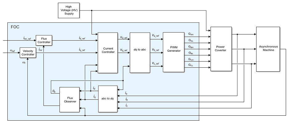
The Controls subsystem contains all four PI controllers. The outer-loop speed PI controller regulates the speed of the motor. The outer-loop flux PI controller regulates the flux of stator. The two inner-loop PI controllers control the d-axis and q-axis currents separately. The command from the outer-loop speed PI controller directly feeds to the q-axis to control torque. The command for the d-axis is nonzero for ASM and is a result of the outer-loop flux PI controller.
The existing PI controllers have the following gains:
Speed PI controller has gains of P = 65.47 and I = 3134.24.
Flux PI controller has gains of P = 52.22 and I = 2790.51.
D-axis PI controller has gains of P = 1.08 and I = 207.58.
Q-axis PI controller has gains of P = 1.08 and I = 210.02.
The controller gains are stored in a Data Store Memory block and provided externally to each PID block. When the tuning process for a controller is complete, the new tuned gains are written to the Data Store Memory block. This configuration allows you to update your controller gains in real-time during the simulation.
Closed-Loop PID Autotuner Block
The Closed-Loop PID Autotuner block allows you to tune one PID controller at a time. It injects sinusoidal perturbation signals at the plant input and measures the plant output during a closed-loop experiment. When the experiment stops, the block computes PID gains based on the plant frequency responses estimated at a small number of points near the desired bandwidth. For this FOC ASM model, the Closed-Loop PID Autotuner block can be used for each of the four PI controllers.
This workflow applies when you have initial controllers that you want to retune using the Closed-Loop PID Autotuner block. The benefits of this approach are:
If there is an unexpected disturbance during the experiment, it is rejected by the existing controller to ensure safe operation.
The existing controller keeps the plant running near its nominal operating point by suppressing the perturbation signals.
When using the Closed-Loop PID Autotuner block for both simulations and real-time applications:
The plant must be either asymptotically stable (all the poles are strictly stable) or integrating. The autotuner block does not work with an unstable plant.
The feedback loop with the existing controller must be stable.
To estimate plant frequency responses more accurately in real time, minimize the occurrence of any disturbance in the FOC ASM model during the experiment. The autotuner block expects the plant output to be the response to the injected perturbation signals only.
Because the feedback loop is closed during the experiment, the existing controller suppresses the injected perturbation signals as well. The advantage of using closed-loop experiment is that the controller keeps the plant running near the nominal operating point and maintains safe operation. The disadvantage is that it reduces the accuracy of frequency response estimation if your target bandwidth is far away from the current bandwidth.
Connect Autotuner with Plant and Controller
Insert the Closed-Loop PID Autotuner block between the PID block and the plant for all four PI controllers, as shown in the FOC ASM model. The start/stop signal starts and stops the closed-loop experiment. When no experiment is running, the Closed-Loop PID Autotuner block behaves like a unity gain block, where the  signal directly passes to
  .
.
View the original control structure for the machine-side converter with four PI controllers.
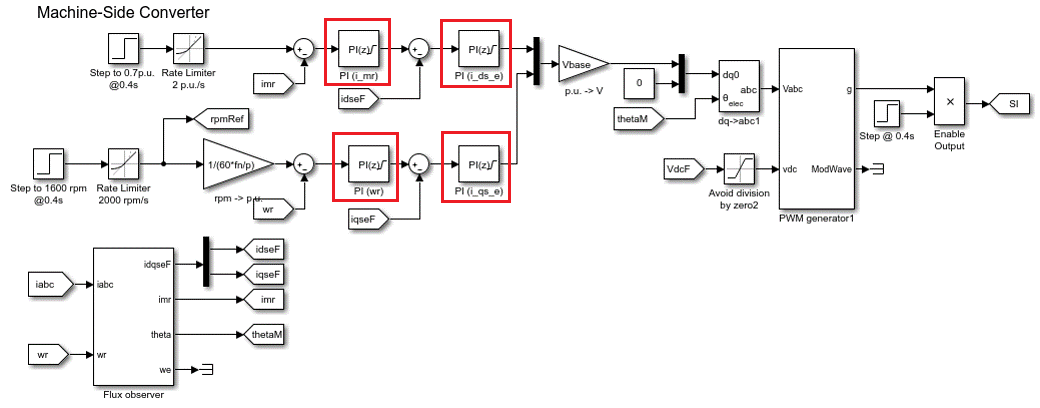
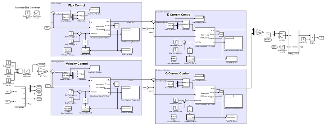
To modify the control structure, incorporate the Closed-Loop PID Autotuner Block to each of the PI controllers. View the modified control structure for the machine-side converter.
Configure Autotuner Block
After connecting the Closed-Loop PID Autotuner block with the plant model and PID block, configure the tuning and experiment settings.
On the Tuning tab, there are two main tuning settings:
Target bandwidth - Determines how fast you want the controller to respond. In this example, choose
5000rad/sec for inner-loop current control and200rad/sec for outer-loop control.
Target phase margin - Determines how robust you want the controller to be. In this example, choose
70degrees for inner-loop current control and90degrees for outer-loop control.
On the Experiment tab, there are three main experiment settings:
Plant Type - Specifies whether the plant is asymptotically stable or integrating. In this example, the FOC ASM model is stable.
Plant Sign - Specifies whether the plant has a positive or negative sign. The plant sign is positive if a positive change in the plant input at the nominal operating point results in a positive change in the plant output when the plant reaches a new steady state. Otherwise, the plant sign is negative. If a plant is stable, the plant sign is equivalent to the sign of its dc gain. If a plant is integrating, the plant sign is positive (or negative) if the plant output keeps increasing (or decreasing). In this example, the FOC ASM model has a positive plant sign.
Sine Amplitudes - Specifies the amplitudes of the injected sine waves. In this example, choose
0.25for the inner-loop controllers and0.01for the outer-loop controllers to ensure the plant is properly excited within the saturation limit. If the excitation amplitude is either too large or too small, it will produce inaccurate frequency response estimation results.
Tuning Cascaded Feedback Loops
Because the Closed-Loop PID Autotuner block only tunes one PI controller at a time, the four controllers must be tuned separately in the FOC ASM model. Tune the inner-loop controllers first, and then tune the outer-loop controllers.
The d-axis current controller is tuned between 3.5 and 3.55 sec.
The q-axis current controller is tuned between 3.6 and 3.65 sec.
The flux controller is tuned between 3.7 and 4.7 sec.
The speed controller is tuned between 4.8 and 5.8 sec.
After tuning each PI controller, the controller gains are updated through the Data Store Memory block.
Simulating Autotuner Block in Normal Mode
In this example, the FOC ASM model is built in Simulink. All four controllers are tuned in one simulation. In addition, speed responses are compared before and after tuning the controllers. Scenarios under test include the acceleration process and torque load changes (magnitude of 1 p.u.).
Simulation of the FOC ASM model usually takes a few minutes on your computer due to the small sample time of the power electronics controller of the motor.
sim(mdl)
logsout_autotuned = logsout;
save('AutotunedSpeed','logsout_autotuned');
The following figure shows the overall simulation result.
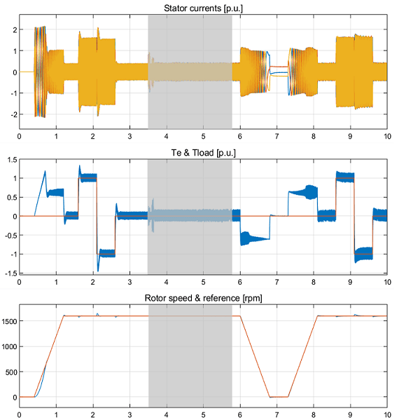
The gray area in the previous figure shows the current and speed responses during tuning, from 3.5 to 5.8 seconds. The changes in current and in motor speed are very small. The motor speed reaches the nominal 1600 rpm before the autotuning process begins.
The four PI controllers are tuned with new gains.
The speed PI controller has gains of P = 158.8 and I = 2110.
The flux PI controller has gains of P = 129.3 and I = 1732.
The d-axis PI controller has gains of P = 1.611 and I = 627.6.
The q-axis PI controller has gains of P = 2.029 and I = 829.9.
The same rotor speed references and torque loads are applied before and after the autotuning process. Plot rotor speed errors with respect to the nominal 1600 rpm before and after the controllers are tuned using the Closed-Loop PID Autotuner block. The speed error curves are aligned in time to compare controller performances side-by-side.
scdfocasmPIDTuningPlotSpeed
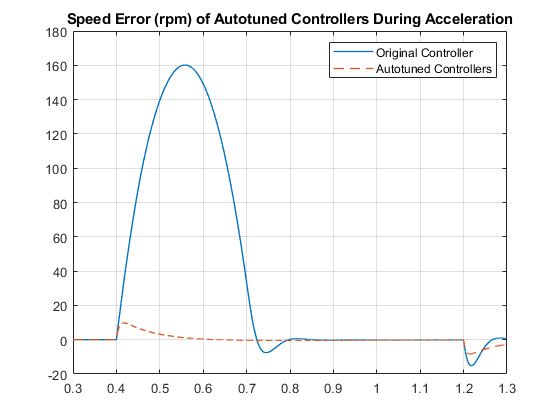
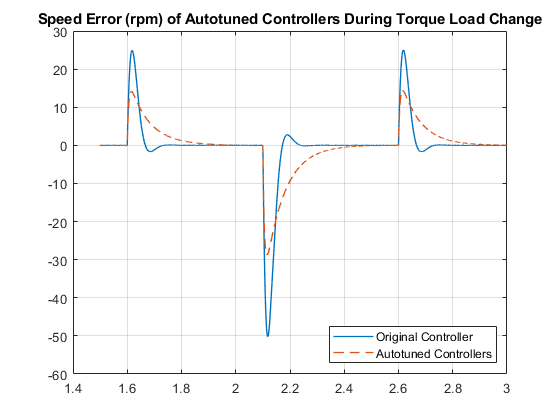
After tuning the controllers, the speed response of the asynchronous motor has a faster transient response and smaller steady-state error during acceleration and when torque load changes.
bdclose(mdl)