Collect Coverage for MinMax Blocks in Collapse Mode
This example shows how to analyze and interpret coverage results for a MinMax block in collapse mode. A MinMax block is in collapse mode when you set the Apply over parameter to Specified dimension.
If there is a single matrix input to the MinMax block, you can choose to apply the chosen function, min or max, over one or all specified dimensions of the input signal. For more information, see Apply over.
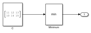
When you use collapse mode, it changes how the MinMax block reports coverage results. This example shows how to collect coverage for a MinMax block that has the Apply over parameter set to Specified dimension. The example model slcoverageMinMaxCollapse contains a Constant block that outputs a 2-by-3 matrix of 8-bit integer values and a MinMax block with the Function block parameter set to min, the Apply over block parameter set to Specified dimension, and the Dimension block parameter set to 1.
Open the Model
Open the model.

On the Modeling tab, click Model Settings. In the Configuration Parameters dialog box, ensure Enable coverage analysis is selected and Structural coverage level is set to Decision. Click Other metrics to expand the list, and ensure Relational boundary is selected. Click OK. In the toolstrip, click Run (Coverage).
Investigate Decision Coverage Results
When the simulation completes, the Coverage Details pane opens. Click the Minimum block to scroll the report to the details for that block.

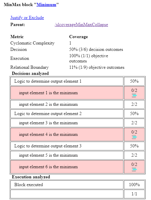
The decision coverage results are 50%. This result is expected because the input signal to the Minimum block connects to a Constant block, so the values do not change during the simulation. The decision coverage table uses single-value indexing, also called linear indexing, even when the signal contains an array that has two or more dimensions. For more information about linear indexing, see the Indexing with a Single Index section of Array Indexing.
The Decisions analyzed table indicates that the Minimum block collapsed one of the dimensions. There are six input elements, but only three output elements, because the MinMax block applied the min function over the columns. The row Logic to determine output element 1 contains two child rows, input element 1 is the minimum and input element 2 is the minimum. In this example, input element 1 is 11, and input element 2 is 10. As a result, input element 2 is the minimum at every time step.
Investigate Relational Boundary Coverage Results
Scroll to the Relational Boundary analyzed table for the same block.

The Relational Boundary analyzed table contains a row for each element of the input array, subtracted by the minimum or maximum of the elements before and after that number, if they exist.
In the first row of the table, input element 1 - min(input elements after input element 1 across collapsed dimension), input element 1 is 11 and the input elements after input element 1 across the collapsed dimension is input element 2, which is 10. The result of this operation is 11 - 10, which equals 1. Because this value is not 0 or -1, which are the values that relational boundary coverage checks for when the signal uses integer data types, the result is that here is no relational boundary coverage for input element 1. The same logic applies to other input elements.
Because the coverage report uses single-element indexing, for the third input element in the relational boundary table, input element 3 - min(input elements after input element 3 across collapsed dimension), input element 3 is 12. Therefore, this statement evaluates to 12 - 14 which is -2. Because this is not equal to -1 or 0, it results in no satisfied relational boundary coverage.
Change the Collapse Dimension
In the model, double-click the Minimum block to open the block dialog. Change the Dimension parameter to 2 and click OK. Simulate the model again by clicking the Run (Coverage) button. After the simulation completes, click the Minimum block to view the block details.

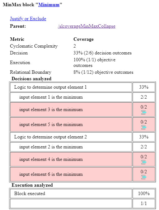
The Decisions analyzed table now contains two tiered rows instead of three, because the Minimum block outputs a two-element vector instead of a three-element vector. Because the Minumum block applies the min function across the rows, the block now takes the minimum of elements from row 1 and row 2 and puts them into a 2-by-1 column vector. Output element 1 is 11, which is the minimum of 11, 12, and 13.
Navigate to the Relational Boundary analyzed table.

Input element 3 has two separate rows. The first row is input element 3 - min(input elements before input element 3 across collapsed dimension). Input element 3 is 12, and the input element before input element 3 across the collapsed dimension is input element 1, which is 11. The result of this row is 12 - 11 = 1, which does not satisfy any relational boundary outcomes. The next row is input element 3 - min(input elements after input element 3 across collapsed dimension). The result of this row is 12 - 13 = -1. Although the outcome of this difference is -1, the corresponding value in the relational boundary table is not satisfied because the decision input element 3 is the minimum did not occur during this time step, and Simulink Coverage only checks the relational boundary outcome if the corresponding decision is true during that time step.
For more information about relational boundary coverage in MinMax blocks, see Collect Relational Boundary Coverage for MinMax Block.
Limitations
You cannot collect relational boundary coverage for a MinMax block with the Apply over parameter set to Specified dimension if the block input is a variable-size signal.