Prepare ASAP2 Data Description File
This example shows how to configure a Simulink® Real-Time™ model so that the build generates an ASAP2 (A2L) data description file for the real-time application. The real-time application models a damped oscillator that feeds into 1-D and 2-D lookup tables, which invert and rescale the input waveform.
Open the Model
This example uses model slrt_ex_osc_cal. To open the model, in the MATLAB® Command Window, type:
model = 'slrt_ex_osc_cal';
open_system(model);

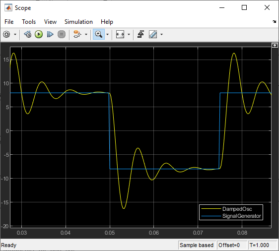


Calibration of parameters reduces the ringing in signals DampedOsc, L_1D, and L_2D.
Initial Setup
Open the model and check for model data.
1. The Model Workspace variables contain these functions:
Kg-- Parameter object for the Gain1 blockDampedOsc,SignalGenerator,L_1D,L_2D-- Signal objects for output signalsLUT_1D_obj,LUT_2D_obj-- 1-D and 2-D lookup tables data respectivelySignalGenerator-- Test input data
2. Set the Default parameter behavior configuration parameter to Tunable.
3. In the Code Mappings Editor — C in Data Defaults, specify the storage class as PageSwitching for Model parameters under Parameters.

Note: The model default setting for parameters sets the storage class as PageSwitching.
Set Up Parameters
Set up parameter tuning by using Simulink® parameter objects.
1. In slrt_ex_osc_cal, on the Modeling tab, click Design > Model Explorer.
2. Select Model Workspace in the Model Hierarchy pane.
3. Make sure that the Kg parameter object exists and has these properties:
Value -- 400
Data type -- double
4. If the parameter object does not exist, add it. On the toolbar, click the Add Simulink Parameter button.
5. Open slrt_ex_osc_cal/Gain1.
6. Make sure that you have set the Gain value to the parameter object Kg.
Set Up Signals
As a best practice, set up signal viewing by using Simulink signal objects.
1. In slrt_ex_osc_cal, on the Modeling tab, click Design > Model Explorer.
2. Select Model Workspace in the Model Hierarchy pane.
3. Make sure that the DampedOsc signal object exists and has these properties:
Minimum -- -10
Maximum -- 10
Data type* -- double
4. Make sure that the SignalGenerator signal object exists and has these properties:
Minimum -- -10
Maximum -- 10
Data type -- double
5. Make sure that the L_1D signal object exists and has these properties:
Minimum -- -15
Maximum -- 15
Data type -- double
6. Make sure that the L_2D signal object exists and has these properties:
Minimum -- -15
Maximum -- 15
Data type -- double
7. If a signal does not exist, add it. On the toolbar, click the Add Simulink Signal button.
8. For each signal, open its Properties dialog box.
9. Make sure that you selected the Signal name must resolve to Simulink signal object and the Test point check boxes.
Set Up Lookup Tables
The example model contains 1-D and 2-D lookup tables.
1. Open the block parameters for the 1-D Lookup Table block.
2. In the Table and Breakpoints pane, verify these settings:
Number of table dimensions -- 1
Data specification -- Lookup table object
Name -- LUT_1D_obj
3. Open the block parameters for the 2-D Lookup Table block.
4. In the Table and Breakpoints pane, check these settings:
Number of table dimensions -- 2
Data specification -- Lookup table object
Name -- LUT_2D_obj
To view the contents of the lookup tables, click Edit table and breakpoints, and then click Plot > Mesh.
Generate Data Description File
Use the Generate Calibration Files tool to generate the required version of ASAP2 file. By default, the addresses for the data elements in the ASAP2 file are set to "0x0000". To replace the addresses with correct values, you can enable the Address replacement option and specify a Symbol file to get the addresses. The symbol file, also known as MAP file, is generated and saved as slrt_ex_osc_cal in the build directory during the model build. For more information about using the tool, see Generate ASAP2 and CDF Calibration Files.
1. On the Real-Time tab, select Run on Target > Build Application.
2. On the C Code tab, select Share > Generate Calibration Files.
3. On the Generate Calibration Files tool, select the Address replacement option and specify the MAP file in the Symbol file field.

You can also generate the ASAP2 file by using the coder.asap2.export function.
coder.asap2.export('slrt_ex_osc_cal', ...
    'MapFile','slrt_ex_osc_cal_sg_rtw/slrt_ex_osc_cal', ...
    'Comments',false);
3. Connect to the target by using a third-party calibration tool.
Close All Open Files
bdclose(model);
See Also
n-D Lookup Table | coder.asap2.export | extractASAP2 | updateASAP2 | RTW.getBuildDir
Topics
- Generate ASAP2 and CDF Calibration Files
- Calibrate Parameters with Vector CANape
- Calibrate Parameters with ETAS Inca