Configure Properties of Formal Requirements
When you create formal requirements with a Requirements Table block, the block also creates requirements that you can configure in the Requirements Editor or the Property Inspector. You can also use the Requirements Editor to link the requirements in Requirements Table blocks to model elements. After you configure your requirements, you can analyze the requirements by using a traceability matrix or traceability diagram.
Open the Requirements in the Requirements Editor
When you load a Simulink® model that contains at least one Requirements Table block,
the Requirements Editor loads the requirements associated with the block. To
open the Requirements Editor, in the Apps tab, click
Requirements Editor. Alternatively, enter
slreq.editor at the MATLAB® command line. You can load one or multiple models.
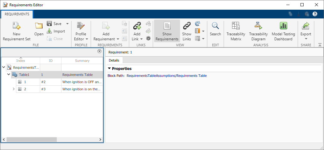
If the models that you load contain at least one Requirements Table block, the Requirements Editor loads each model as a requirement set. The Requirements Editor lists the Requirements Table blocks contained in each model as Import nodes that you can expand to view the requirements. The Summary column of the node is the name of each block.
For example, load the model used in Use Assumptions in an Example Model and expand the Import node Table1 to see the requirements.
Simulink stores the requirement set of each block in the model. When you load the model, Requirements Toolbox™ creates a copy of the requirement set file in memory. However, Requirements Toolbox does not create a separate requirement set file.
If you load a model that contains more than one Requirements Table block, the Requirements Editor loads the requirement sets of each Requirements Table block. You cannot specify individual Requirements Table blocks to load from a given model.
Manage Requirements In the Requirements Editor and Property Inspector
After loading the model, you can use the Requirements Editor and the Property Inspector to modify the requirement type, custom ID, description, rationale, or keywords for each requirement.
Use the Requirements Editor
In the Requirements Editor, expand the Import node to see the requirements. Click a requirement to modify its properties.
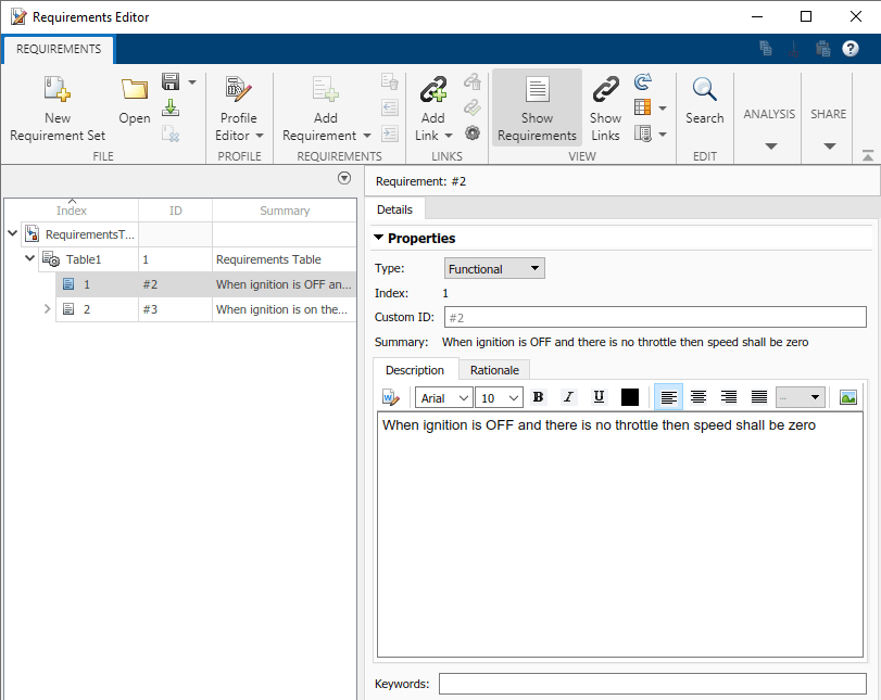
You can then modify the Type, Custom ID, Description, Rationale, Keywords, and Comments properties. Use the Type property to specify the role of the requirement. See Requirement Types. Use the Custom ID, Description, Rationale, Keywords, and Comments properties to add text-based details to requirements that can help you locate requirements and convey useful information.
When you add or remove requirements in a block, the requirements update in the editor. If you change the name of the summaries of each requirement in the block, the Summary property automatically updates. When you first create a requirement, the Description field has the same value as the Summary property.
Use the Property Inspector
To use the Property Inspector:
Open the model that contains the Requirements Table block.
Open the Requirements Table block.
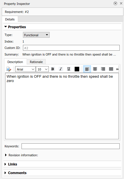
Open the Property Inspector. In the Modeling tab, in the Design Data section, click Property Inspector.
In the Requirements tab of the block, click the requirement.
The Property Inspector shows the same properties that appear in the right pane of the Requirements Editor.
Link Requirements
You can use the Requirements Editor to add incoming or outgoing links to requirements in the Requirements Table block. To create incoming links from the block requirements to another element in a model:
In the model, select a model element.
In the Requirements Editor, select a requirement.
Click Add Link > Link from Selection in Simulink.
For more information about creating links, see Create and Store Links.
If you save the model with a new name, the software creates a copy of the link set file that has the same name of the model file. However, if the requirements have any incoming links, a dialog box asks whether to copy or clear the links when you save the model. Click Update incoming links to copy the links or Disconnect incoming links to clear the new link set.
When you link requirements in a Requirements Table block, the software creates a separate link set file with the same name as the model by default. If you do not want to create a separate link set file, you can also store the links internally as part of the model:
In the Apps tab, click Requirements Manager.
In the Requirements Browser, set View to
Links.In the Requirements tab, in the Settings section, click Link Settings > Default Link Storage.
In the Requirements Settings window, in the Storage tab, select Store internally (embedded in Simulink diagram file).
For more information, see Link Storage.
Create a Traceability Matrix and Traceability Diagram
After linking the requirements, you can create a traceability matrix or a traceability diagram.
Create a Traceability Matrix
To access the Traceability Matrix window, use one of these approaches:
In the Requirements Editor, click Traceability Matrix.
At the MATLAB command line, enter:
slreq.generateTraceabilityMatrix
To create a traceability matrix, select the model file and the SLREQX file of the same name. For more information, see Track Requirement Links with a Traceability Matrix.
Create a Traceability Diagram
To create a traceability diagram, use one of these approaches:
In the Requirements Editor, select the requirement or Import node and, in the Analysis section, click Traceability Diagram.
In the Requirements Editor, right-click the requirement set or block node and select View Traceability Diagram.
At the MATLAB command line, enter:
slreq.generateTraceabilityDiagram
For more information, see Visualize Links with Traceability Diagrams.