Three-Phase Autotransformer with Tertiary Winding
The Specialized Power Systems library will be removed in R2026a. Use the Simscape™ Electrical™ blocks and functions instead. For more information on updating your models, see Upgrade Specialized Power System Models to use Simscape Electrical Blocks.
Libraries:
Simscape /
Electrical /
Specialized Power Systems /
Power Grid Elements
Description
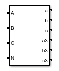
The Three-Phase Autotransformer with Tertiary Winding block represents a three-phase autotransformer. The high-voltage side is identified by the A, B, and C ports, the low-voltage side by the a, b, and c ports, and the tertiary-winding by the a3, b3, and c3 ports.
Equivalent Circuit
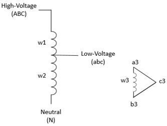
The equivalent circuit of one phase is shown in the diagram. Each phase consists of three coupled windings: a series winding between the high-voltage terminals and low-voltage terminals, a common winding between the low-voltage terminals and the neutral terminal, and a tertiary winding connected in Delta D1.

The resistances and leakage inductances of the three windings are determined from short-circuit test parameters using the following standard equations:
R1 = (R12*(1+k)/(1-k) + R13 - R23_pu)/(1-k)/2 R2 = (R12 - R13 + R23_pu)/(1-k)/2 R3 = (-R12 + R13 + R23*(1-2*k))/(1-k)/2
L1 = (L12*(1+k)/(1-k) + L13 - L23)/(1-k)/2 L2 = (L12 - L13 + L23)/(1-k)/2 L3 = (-L12 + L13 + L23*(1-2*k))/(1-k)/2
where:
R12, R13, and R23 are the RHL, RHT, and RLT short-circuit test resistances.
L12, L13, and L23 are the LHL, LHT, and LLT short-circuit test inductances.
k is the voltage ratio between the high-voltage side and low-voltage side nominal voltages.
All parameters are in pu based on the nominal power and nominal voltage of the windings.
The standard equations listed above may produce negative winding resistances and inductances. Although negative values are permitted in phasor models (at 50 Hz or 60 Hz) using algebraic equations, these negative parameters may result in numerical instability in EMT models that use differential equations. In this case, a warning message suggests you modify the R23 or the L23 parameter and proposes a range of values that produce positive resistance and inductance values.
To avoid the limitations of the standard model that may result in negative resistances or very uneven sharing of losses between winding 1 and winding 2, you may choose an alternate model for computing winding resistances. This alternate model assumes that the Joules losses corresponding to R12 are equally shared between winding w1 and winding w2 (R2 = R1), which is close to real life. R1 and R2 are in pu and are computed as follows:
R1 = R12/2/(1-k)^2 R2 = R1
R3 is adjusted to obtain the specified R13 value, as given by the following equation:
R3 = R13 - R1*(1-k)^2 - R2*k^2.
Although this model returns an error on R23, this has a limited impact because it affects only the tertiary winding, which is frequently unloaded or feeds a maximum of 10% of autotransformer nominal power. This model more accurately represents the sharing of currents between winding 1 and winding 2 for DC or very low-frequency phenomena. For example, during a geomagnetic disturbance that produces very low-frequency earth electrical fields, the resulting geomagnetically induced currents (GICs) throughout the network are dependent on the DC autotransformer model.
Ports
Conserving
Parameters
Extended Capabilities
Version History
Introduced in R2021b
