Inductive Rotor Position Sensor
Inductive rotor position sensor with four inductive coils
Libraries:
Simscape /
Electrical /
Sensors & Transducers
Description
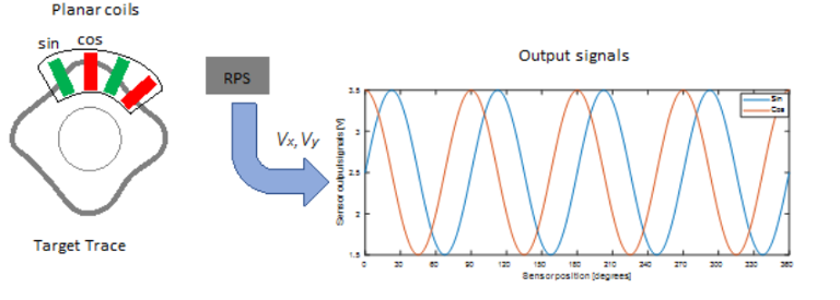
The Inductive Rotor Position Sensor block uses the theory of eddy current losses to obtain the rotor position. It consists of four planar coils and a target trace that detect the rotor position. The target trace is shaped in a sinusoidal way and made from conductive material. The distance between the four planar coils is equivalent to 90 degrees of one cycle.

Equations
The voltages between the elements of the sensor are described by the equations:
where:
vx is the cosine voltage.
vy is the sine voltage.
Ax and Ay are the voltage amplitudes for the x and y axes that reflect the sensitivity mismatch.
Vx0 and Vy0 are the voltage offsets for the x and y axes.
N is the number of pole pairs.
θ is the mechanical position.
β is the quadrature error.
K is the tumbling factor.
The block uses this equation to decode the angle:
This figure shows the effects of the tumbling factor:

Variables
To set the priority and initial target values for the block variables before simulation, use the Initial Targets section in the block dialog box or Property Inspector. For more information, see Set Priority and Initial Target for Block Variables.
Nominal values provide a way to specify the expected magnitude of a variable in a model. Using system scaling based on nominal values increases the simulation robustness. You can specify nominal values using different sources, including the Nominal Values section in the block dialog box or Property Inspector. For more information, see System Scaling by Nominal Values.
Ports
Conserving
Output
Parameters
Extended Capabilities
Version History
Introduced in R2020a
