Getting Started with Simulink Coder Support Package for VEX EDR V5 Robot Brain
This example shows you how to use Simulink® Coder™ Support Package for VEX® EDR V5 Robot Brain to run a Simulink model on a VEX V5 Robot Brain.
Introduction
Simulink Coder Support Package for VEX EDR V5 Robot Brain enables you to create and run Simulink models on a V5 Robot Brain. The support package includes a library of Simulink blocks for configuring and accessing VEX peripherals and competition specific convenience blocks.
In this example, you will learn how to configure two simple Simulink models:
In the first model, you will set a DC motor, connected to a 3-wire port on the V5 Robot Brain, to rotate at its maximum speed. You generate code for V5 Robot Brain and run the generated code on the hardware.
In the second model, you will simulate the behavior of a servo motor, which can be connected to a 3-wire port on the V5 Robot Brain, to control the servo angle when a button is pressed. You visualize the changes to the servo angle based on to the status of the button, in the simulated model itself.
Prerequisites
If you are new to Simulink, watch the Simulink Quick Start video.
Required Hardware
To run this example, you need the following hardware:
VEX EDR V5 Robot Brain
DC motor and Motor Controller 29
V5 Robot Battery
USB A to Micro Cable
Task 1 - Review the Block Library for the VEX EDR V5 Robot Brain Support Package
1. Enter simulink at the MATLAB® prompt. This opens the Simulink Start Page.
2. In the Simulink model, from the Simulation tab, navigate to Library Browser > Simulink Coder Support Package for VEX EDR V5 Robot Brain.
3. Open the Actuators category and double-click the DC Motor block and the Servo Motor block. Review the description of the blocks and the input parameters.
Task 2 - Create a Model for DC Motor Connection
In this task, you will create a simple Simulink model that sets a DC motor, connected to the 3-wire port B on the VEX V5 Robot Brain, to rotate at maximum speed (the DC Motor block accepts speeds between -127 and 127).
1. On the Simulink start page, navigate to Simulink Coder Support Package for VEX EDR V5 Robot Brain and select the Basic Model template.
2. Delete the Servo Motor block from the Add VEX Actuators & Outputs area in the template.
3. Launch the Simulink Library Browser and navigate to the library Simulink Coder Support Package for VEX EDR V5 Robot Brain.
4. Drag the DC Motor block (from the Actuators category) to the Add VEX Actuators & Outputs area in the Simulink model. Rename it to SetMotor. Set the value of the Port parameter to B.
5. Connect the input port of SetMotor to the Deployment signal in the template.
6. Double-click the Pulse Generator block in the Add Simulation Sources area, and ensure that the Amplitude value is set to 1.
7. Ensure that the switch position of the Manual Switch block is towards the Add Simulation Sources area.
8. Save the Simulink model.
Task 3 - Set Up the VEX V5 Robot Brain and DC motor
In this task, you will connect the VEX V5 Robot Brain to the host computer and connect a DC motor to the appropriate port on the hardware.
1. Connect the V5 Robot Brain to your computer using the USB cable.
2. Connect the fully-charged V5 Robot Battery to the V5 Robot Brain.
3. Switch on the V5 Robot Brain.
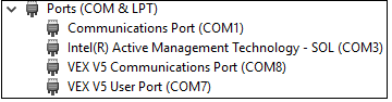
On Windows, V5 Robot Brain appears as a COM device with the label VEX V5 Communications Port (COM#) in the Device Manager.
4. Connect the DC motor to the 3-wire port B on VEX V5 Robot Brain. Use the Motor Controller 29 cables to establish the connection between the motors leads and the port on V5 Robot Brain.
Task 4 - Configure and Run the Model on V5 Robot Brain
1. Open the Modeling tab and press CTRL+E to open Configuration Parameters dialog box..

2. In the Configuration Parameters dialog box, navigate to the Hardware Implementation pane:
Set the Hardware board to VEX V5 Robot Brain.
In the Target Hardware Resources section, set the Build options to Build, load and run to automatically download the generated binary file to the connected V5 Robot Brain.
3. On the Solver pane, select the option Treat each discrete rate as a separate task.
4. Click OK.
5. Open the Hardware tab and click Build, Deploy & Start. The model is automatically deployed to the VEX V5 Robot Brain connected to the host computer.

If there is a problem while deploying the model to the V5 Robot Brain, a warning will be displayed in the Diagnostic Viewer. The possible causes of failure to successfully deploy are:
The V5 Robot Brain needs to be rebooted.
The COM Port is busy.
The Build Action in the Configuration Parameters > Hardware Implementation > Build Options drop-down is set to Build, and not Build, load, and run.
6. Observe that the DC motor connected to the 3-wire port B rotates continuously.
A pre-configured model (vexv5_gettingstarted_dcmotor) is included for your convenience.

Task 5 - Create a Model for Simulating the Servo Motor Behavior
In this task, you will create a simple Simulink model and simulate the behavior of a servo motor connected to V5 Robot Brain. The logic is designed to turn the servo angle by 45 degrees each time you press a button. This button (used for simulation) can function like the button present on the actual gamepad (V5 Controller). You can also visualize the changes to the servo angle in the simulated model itself based on the changes to the input.
1. On the Simulink start page, navigate to Simulink Coder Support Package for VEX EDR V5 Robot Brain and select the Interactive Model template.
2. Double-click the Gain block in the Design your algorithm here area in the template, and set the Gain value to 45. Click OK.
3. Ensure that the switch position of the Manual Switch block is towards the Add Simulation Sources area.
4. Click the Run icon on the Simulink toolbar.
5. When the simulation starts, click the Button block in the Add Simulation Sources area. You can see that the angle displayed in the Half Gauge block (labelled as Servo Angle) changes to 45 degrees.
6. Click the Button block again to simulate the button-released state. You can see that the angle is reversed back to zero degrees.
A pre-configured model (vexv5_gettingstarted_servodashboard) is included for your convenience.
Other Things to Try with the Simulink Templates and Blocks for VEX V5 Robot Brain
Create and run a Simulink model that rotates two DC motors in opposite directions simultaneously (like a Skid Steer drivetrain).
Create and run a Simulink model that uses a signal from a digital sensor connected to V5 Robot Train to decide the turn angle of the servo motor.
You can also select a web site from the following list:
Americas
- América Latina (Español)
- Canada (English)
- United States (English)
Europe
- Belgium (English)
- Denmark (English)
- Deutschland (Deutsch)
- España (Español)
- Finland (English)
- France (Français)
- Ireland (English)
- Italia (Italiano)
- Luxembourg (English)
- Netherlands (English)
- Norway (English)
- Österreich (Deutsch)
- Portugal (English)
- Sweden (English)
- Switzerland
- United Kingdom (English)