Read Data from IMU and Environmental Sensors
This example shows how to use C2000™ Microcontroller Blockset to read data from the BMI160 Inertial Measurement Unit (IMU) sensor and BME280 Environmental sensor that are part of the BOOSTXL-SENSORS BoosterPack™ plug-in module.
The example also shows how to read data from another BMM150 geomagnetic sensor connected as a breakout board to F28379D LaunchPad.
Required Hardware
Texas Instruments™ F28379D LaunchPad.
BOOSTXL-SENSORS BoosterPack™ plug-in module, which includes built-in BMI160 Inertial Measurement Sensor, BMM150 Geomagnetic Sensor and BME280 Environmental Sensor.
BMM150 Geomagnetic Sensor on an I2C-based board to be connected as a breakout board to F28379D LaunchPad.
Introduction
This example provides three Simulink models that use TI Delfino F28379D Launchpad as the Hardware board:
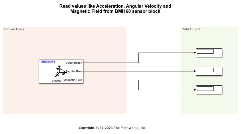
c28x_i2c_bmi160_sensor helps you to read acceleration, angular rate and magnetic field as measured from both BMI160 and BMM150 sensors in the BOOSTXL-SENSORS module
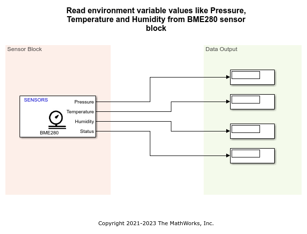
c28x_i2c_bme280_sensor helps you to read digital pressure and relative humidity as measured from a BME280 sensor in the BOOSTXL-SENSORS module
c28x_i2c_bmm150_sensor helps you to read magnetic field as measured from a BMM150 sensor connected as a breakout board to F28379D LaunchPad
Model Configuration for Reading Data from BMI160 Sensor and BME280 Sensor
The model provided in this example for reading data from BMI160 sensor uses the corresponding block, BMI160 provided with the blockset.
Open the c28x_i2c_bmi160_sensor model.

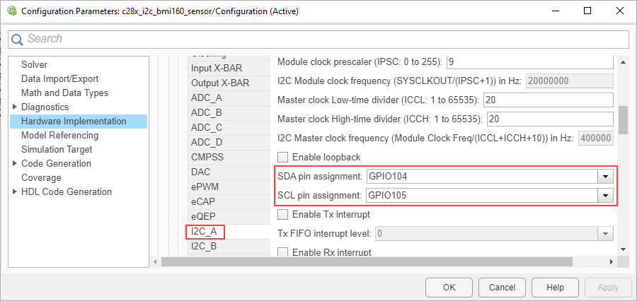
In the BMI160 block in the model, the I2C module parameter is set to I2C_A. Therefore, to change the clock frequency, if required, change the settings for the same. To do this:
1. Go to Hardware tab, and click Hardware Settings to open the Configuration Parameters dialog box.
2. Go to Hardware Implementation > Target hardware resources, and select I2C_A tab.
3. Edit the values to change the clock frequency as required.

4. Click Apply and then *OK.
The other model provided in this example for reading data from BME280 sensor uses the corresponding block, BME280 provided with the blockset.
Open the c28x_i2c_bme280_sensor model.

In the BME280 block in the above model, the I2C module parameter is set to I2C_A. Therefore, to change the clock frequency, if required, change the settings by following the same steps as described for BMI160.
You can also use the different options under Advanced settings inside the BME280 block to change the values for the filtering and sampling factors.
Note: The I2C address parameter value selected in each of the blocks (BMI160 and BME280) in the two models corresponds to the information provided in the Schematics section of the BOOSTXL-SENSORS BoosterPack Plug-in Module User's Guide.
Complete Hardware Connections and Read Data from BMI160 Sensor
After you complete the configurations settings for the c28x_i2c_bmi160_sensor model, perform these steps:
1. Connect the BOOSTXL-SENSORS plug-in module to the F28379D LaunchPad. Connect GPIO104 and GPIO105 pins on the F28379D Launchpad to the J1.10 (SDA) and J1.9 (SCL) pins respectively on the BOOSTXL-SENSORS, and complete the other required connections like VDD and GND. For more details, refer to the Schematics section of the BOOSTXL-SENSORS BoosterPack Plug-in Module User's Guide.
2. Connect the F28379D LaunchPad to the host computer.
2. In the Configuration Parameters window of c28x_i2c_bmi160_sensor model, click Hardware Implementation and navigate to Target hardware resources > External mode, and set the Serial port in MATLAB Preferences parameter to the corresponding COM port to which the Launchpad is connected. The COM port is available at Device Manager > Ports (COM & LTP) in Windows.
3. Select appropriate GPIO pins for SDA and SCL in Hardware Implementation > I2C_A pane, to communicate with BOOSTXL-SENSORS based on the actual hardware connections from the F28379D Launchpad.

4. In the Hardware tab of Simulink model, click Monitor & Tune. You can observe from the Diagnostic Viewer that the code is generated for the model and the host connects to the target after loading the generated executable.
5. Rotate the board about its axis. You can observe that the value displayed in the Display block connected to Angular Rate output of the block is changing.
6. Change the orientation of the board. You can observe that the value displayed in the Display block connected to Acceleration output of the block is changing.
Complete Hardware Connections and Read Data from BME280 Sensor
After you complete the configurations settings for the c28x_i2c_bme280_sensor model, perform the same steps 1 to 4 as described in the previous section to specify the connections and run the model in External mode.
Then, observe the value displayed in the Display block connected to Pressure, Temperature, and Humidity output ports of the block. These values correspond to the current environmental conditions.
Model Configuration for Reading Data from BMM150 Sensor Connected as Breakout Board
The model provided in this example for reading data from BMM150 sensor uses the corresponding block, BMM150 provided with the blockset.
Open the c28x_i2c_bmm150_sensor model.

In the BMM150 block in the above model, the I2C module parameter is set to I2C_A. Therefore, to change the clock frequency, if required, change the settings by following the same steps as described for BMI160.
You can also use the different options under Preset value parameter inside the BMM150 block to specify the optimum operating condition.
The board that you use can be a digital compass sensor based on BMM150 that uses an I2C interface. Refer to the board's specifications for I2C connection to F28379D LaunchPad, and specify the value for I2C address parameter accordingly.
Complete Hardware Connections and Read Data from BMM150 Sensor
After you complete the configurations settings for the c28x_i2c_bmm150_sensor model, perform these steps:
1. Connect the I2C-based board with the BMM150 sensor, to the F28379D LaunchPad, and complete the other required connections.
2. Connect the F28379D LaunchPad to the host computer.
2. In the Configuration Parameters window of c28x_i2c_bmm150_sensor model, click Hardware Implementation and navigate to Target hardware resources > External mode, and set the Serial port in MATLAB Preferences parameter to the corresponding COM port to which the Launchpad is connected. The COM port is available at Device Manager > Ports (COM & LTP) in Windows.
3. Select appropriate GPIO pins for SDA and SCL in Hardware Implementation > I2C_A pane, to communicate with I2C-based interface based on the actual hardware connections from the F28379D Launchpad.
4. In the Hardware tab of Simulink model, click Monitor & Tune. You can observe from the Diagnostic Viewer that the code is generated for the model and the host connects to the target after loading the generated executable.
5. Observe the current value in the Display block connected to Magnetic Field output of the block. Change the position of the board. You can observe that the value displayed in the Display block is changing.