5G Beam Management in MATLAB
Overview
In this webinar, we introduce 5G New Radio (NR) beam management procedures at the physical layer. Operation at millimeter-wave frequencies require beam management procedures for initial access in 5G NR. We will cover the stages of beam sweeping, beam measurement, beam determination and beam reporting for such a system. We will also discuss differences in these procedures for Standalone (SA) and non-standalone (NSA) modes.
Highlights
Using reference designs from 5G and Phased Array System Toolboxes, we highlight
- Initial access procedures including transmit/receive point (TRP) beam sweeping
- UE-end beam sweeping to establish a beam pair link
- Using synchronization signal blocks (SSB), for both azimuth and elevation plane sweeps
- Transmit-end beam refinement using channel state information reference signals (CSI-RS)
About the Presenter
Amit Kansal joined MathWorks in 1998. He now serves as a development manager, leading the team that produces products like Communications Toolbox. Over the past decade, he has helped initiate and develop LTE, WLAN and 5G toolboxes. Prior to joining MathWorks, Amit worked as an associate RF engineer at Nextel (now Sprint). He holds an M.S.E.E. from State University of New York, Buffalo, and a B.Tech. (EE) from Delhi College of Engineering, Delhi, India.
Recorded: 20 Nov 2020
Hello, everyone. I'm Amit Kansal, communications development manager at MathWorks. Today, I will be talking about beam management procedures and the physical layer for 5G new radio communication systems.
The agenda of the webinar includes a brief introduction to beam management. We then take a deep look at two procedures using 5G toolbox, namely synchronization signal blocks based beams sweeping at both transmit and receive ends to establish a beam pair link, and then transmit end beam refinement using channels state information reference signals once the link has been established. Finally, we summarize and offer links for some more information.
The support for millimeter wave frequencies requires directional links, which led to the specification of beam management procedures for initial access in New Radio. Beam management is a set of layer 1 and layer 2 procedures to acquire and maintain a set of beam pair links, a beam used at gNodeB paired with a beam used at the UE.
Beam management procedures are applied for both downlink and uplink transmission and reception. These procedures include beam sweeping, beam measurement, beam determination, beam reporting, and beam recovery.
The technical report 38.802 defines beam management as a set of three procedures. Procedure 1 focuses on the initial acquisition based synchronization signal blocks. During initial acquisition, beam sweeping takes place at both transmit and receive ends to select the best beam pair based on reference signal received power measurements.
Procedure 2 focuses on transmit-end beam refinement, where the beam sweeping happens at the transmit end by keeping the received beam fixed. The procedure is based on non-zero power CSIRS for downlink, and sounding reference signals for the uplink.
Procedure 3 focuses on receive-end beam adjustment where the beam sweeping happens at the receive end, given the current transmit beam. Let us look at synchronization signal block based beam sweeping employed during initial access as a UE enters a new area of coverage.
The timing diagram for standalone operation covers the different phases of beam management as follows. For beam sweep and measurement, SS bursts are sent from gNodeB to the UE, with different beams for each SS block within a burst.
For beam determination, the UE decides the best beam based on the reference signal received power measurements. For beam reporting, gNodeB associates RACH occasions, or transmission time opportunities with particular SSB indices.
The RACH preambles received by the gNodeB at a particular time instant come from the UE that pick that SSB index that has the strongest beam. In this way, the beam is reported back to the gNodeB for subsequent transmissions.
New Radio specifies the number of SS blocks per burst based on the operating frequency. There can be a maximum of 4, 8 or 64 blocks within a burst. Each SS block within a burst set is beam formed in a different direction. We now transition to the shipping example on SSB based beam sweeping in 5G toolbox.
At the MATLAB command window, I open the doc browser to navigate to the example within the 5G toolbox Since this is focused on the downlink, we look at the downlink physical signals category, and open the NR SSB beams sweeping example. In this example, we generate a synchronization signal burst and beam form each of the SSBs within the burst, to sweep both azimuth and elevation directions.
The system transmits this beamform signal over a scattering channel. And the received signal is processed over multiple receive-end beams. The reference signal received power is measured for each transmit-receive beam pairs, and the beam pair link with the maximum RSRP is used.
The main processing steps are highlighted as per the schematic shown here, with the beam management ones highlighted in color. We see the simulation parameters which are user modifiable to offer a selection of the operating frequency, SS block pattern, and length, transmit and receive arrays, and sweep parameters.
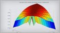
It configures the SS burst generation with a periodicity of 20 milliseconds, and sets up a scattering MIMO channel with uniform rectangular arrays or uniform linear arrays, both with isotropic antenna elements. The resulting SSB burst waveform is as shown in this graphic.
This has not yet been beamformed. As we can see for a 30 kilohertz sub carrier spacing, we see the 8 SS blocks occupying about 5 milliseconds of time over a full radio frame. To achieve transmit-receive point beam sweeping, we beamform each SSB within the generated burst using analog beamforming.
Based on the number of blocks in the burst and the sweep ranges, we determine the azimuth and elevation directions for each beam. Individual blocks within the burst are each sent in the direction of the beams over the spatially aware scattering channel. The dual end beam sweeping is shown by this animation. We depict the sweeps at both the gNodeB and UE as follows.
For a procedure, P1, each of the n beams that are transmitted are transmitted m times, so that each transmit beam can be received over the m received beams. The diagram reveals the time taken for the dual sweep. And in this simple scenario, we can assume that beams S3 and U2 are the selected beam pair link.
The receive processing of the transmitted burst includes the fading channel, an additive white Gaussian noise, receive end beamforming, timing correction, OFDM demodulation, extraction of the known SSB grid, and measurement of the RSRP, based on the specified measurement mode. This processing is repeated for each of the received beams.
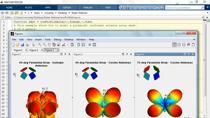
After the dual end sweep completes and the measurements are made, the best beam pair link based on the RSRP measurement is reported at the command window. As visuals, the example offers the transmit and receive array beam patterns, and also the spatial scene, which includes a combined view of the arrays along with the selected beams and scatterers.
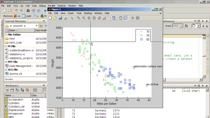
The example offers easy parameter tunability. We consider a case where we modify the scatter location and rerun the example to indicate the modified beam pair link. As the scene shows, with the modified scatter location, the identified beam pair also modifies.
Now, let's look at CSI-RS based transmit-end beam refinement procedure, once the initial connection has been established, as we saw with the SSB based beam sweeping. This is the P2 procedure described earlier. Once the initial beam pair links are established, we can perform beam refinement to further improve the connection. Using digital beam forming, this allows the use of narrower beams to limit interference from multiple users.
We highlight a downlink transmit end beam refinement procedure using the channel state information reference signals from 5G toolbox. Beamforming is enabled by using components from the phased array system toolbox.
The example uses the following schematic, where the beam management enabling components are highlighted in color. Due to digital beamforming, the generated CSI-RS signal is first beamformed before OFDM modulation. The modulated signal is transmitted across the scattering channel, and white Gaussian noise is added.
At the receiver, timing synchronization and OFDM demodulation are performed before receive beamforming. Beam measurement and beam determination follow to get the refined transmit beat. Let us look at the example closely.
So this is the second example, shipping with 5G toolbox on beam management. And this figure shows four non-zero power CSI-RS resources being transmitted in four different directions, these four directions are within the initial beam identified by the SSB sweeps.
As before, as we look over the construction or the layout of the example, we first generate the CSI-RS resources. We then configure transmit and receive antenna arrays, similarly using both uniform rectangular arrays or uniform linear arrays with isotropic elements. And we also configure the scatterers within the spatial scene.
The beam directions are calculated for all active CSI-RS resources within the angular range covered by SSB transmit beam. The system loops over all CSI-RS resources and applies digital beamforming to all active resources. The digital beamforming is used. We perform OFDM modulation, to generate the time domain waveform. We apply the scattering MIMO channel, add noise, and perform timing synchronization at the receiver.
After the OFDM demodulation, we perform digital beamforming by applying steering weights. We again plot the spatial scene to depict the scenario which includes both transmit and receive antenna arrays, scatter positions, and their paths, and all of the beam patterns. For beam determination, for a given receive beam, UE measures the reference signal received power for all CSI-RS resources.
The maximum RSRP value from the measurements, suggests the best beam, which is reported to the command window. We note the refined beam width in comparison to the initial SSB beam, and see that the process has yielded a refinement within the beamwidths. Similar to the SSB example, this example also offers easy tuning of parameters, the number of CSI-RS resources, array configurations, and scatterers.
In summary, beamforming and beam management is an integral part of 5G New Radio. We looked at the initial access procedure of beam sweeping at both transmit and receive ends to establish a beam pair link. We also looked at transmit end beam refinement for improved performance. We showed how 5G and phased array system toolboxes make the modeling and analysis simpler for users with easy to use components.
I want to thank you for your time.
Hello, my name Houman Zarrinkoub. I'm product manager for all the wireless products and MathWorks. I want to thank you, Amit Kansal, my colleague and friend, for that detailed presentation. We decided to do a tag team on this particular webinar. And I will now go through the section that we call how to learn more.
As you notice, the 5G NR beam management relates to the new functionality the, 5G New Radio, that is presented in MathWorks 5G toolbox. So the flagship product for all 5G functionalities: 5G toolbox. You can access the 5G toolbox by going to mathworks.com/products./5g.
And not only we give you a full representation of all what's in 5G toolbox and documentation, we have a short video we can take a look at for the highlights. And our friend, Mark, has provided a nice 5G explain video series that goes through a different technical aspects of 5G toolbox, including the synchronization burst and all that stuff that Amit mentioned.
So if you want to get some basic prerequisite introduction into the product and 5G technology, you can use a 5G toolbox, and these 5G explained video series to get ready for the more advanced topics.
Also, Amit mention the beamforming and the use of phase array system toolbox in a lot of the examples that Amit mentioned. I, myself, today webinar on 5G beamforming on July of this year. And also, we have a lot of material that is featured in the wireless communications solution page you notice down here. mathworks.com/solution/wireless-communication.
And in there, you can find a lot of links to different aspects of beamforming in various products, including phase array system toolbox that I highlight here. Now, 5G is the standard that is the topic of this particular webinar.
But I just wanted to show that MathWorks provide standard based functionality beyond 5G. In 2013, '14, we introduced the 4G LTE functionality in 2016 WiFi or WLAN. And these are three standard based products that we support in MathWorks. So if you go to mathworks.com, you'll notice that we have 5G toolbox, LTE toolbox, and WLAN toolbox.
Also, other standards that we support include Bluetooth and ZigBee. These are downloadable add-ons to communications toolbox. So if you go to communications toolbox, you notice that there is a Bluetooth add-on library. You can download that right from communications toolbox, and the same for ZigBee. So all I'm trying to say is that beyond the functionality of 5G, we provide the standard support for multiple standards.
And not only do standards for wireless communication, which is reflected by this part of this pie chart, if you will, which mentioned here 5G, WiFi, LTE, Bluetooth. We also have other functionalities that, as you notice, for example, a unified RF baseband and antenna model. We have products for like antenna toolbox and phase array toolbox for antenna and array processing. Communication toolbox provide for modulation coding, channel modeling, and all the aspects for any communication links.
And we have RF toolbox and blocksets for modeling the RF processing chain and the RF front end. So anything that has to do with unifying going beyond baseband, and going to RF and antenna is provided also by MathWorks tools. And not only on top, where we provide standard based digital and RF and antenna processing for modeling and simulation, we also have workflow path to implementation on testing.
So you can use our tools to not only model and simulate, but also automatic C or HDL cod generation for implementing those algorithms on processors or FPGA /ASIC, as well as testing capabilities, connectivity to what instruments, and software-defined radios to test your device on their test, and get to verify if what you have done is done properly.
So these are the three areas of wireless communication that we have solutions for. And we focus today on 5G and the beam management aspect. But the area that we have material for is large. And that's one example. In 2020, we have organized once a month a particular webinar that talks about what aspects of those three pie chart areas you saw earlier.
So in April, our friend, Mark, did a 5G toolbox webinar that was about all the functionality of 5G toolbox. Myself and Eric, my friend, did a 5G waveform generation over-the-air testing webinar. It connects 5G waveforms with RF instruments to transmit and receive a 5G waveform from the RF instruments and perform testing.
We had a wireless connectivity webinar that talks about WiFi, NB-IoT, ZigBee, and other standards that relate to wireless connectivity. I did a 5G hybrid beamforming webinar to go through different hybrid beamforming and classical beamforming functionality and design procedures. Our friend, Georgia, did a 5G urban communication with ray tracing. And my friend, Jack, did a decode 5G NR wireless signals on an FPGA, which relates to wireless HDL toolbox.
And also on October, our friend, Georgia, did RF and antenna design for wireless presentation. In November, we're doing this presentation is about 5G beam management. And on December, our friend, Mike, is doing a Bluetooth library introduction.
So based on all those three area, standard, prototyping, and testing, and unified RF baseband antenna, we're providing a full slew of webinars to get you up and running with your design. Thank you very much.
Featured Product
5G Toolbox


Seleccione un país/idioma
Seleccione un país/idioma para obtener contenido traducido, si está disponible, y ver eventos y ofertas de productos y servicios locales. Según su ubicación geográfica, recomendamos que seleccione: United States.
También puede seleccionar uno de estos países/idiomas:
América
- América Latina (Español)
- Canada (English)
- United States (English)
Europa
- Belgium (English)
- Denmark (English)
- Deutschland (Deutsch)
- España (Español)
- Finland (English)
- France (Français)
- Ireland (English)
- Italia (Italiano)
- Luxembourg (English)
- Netherlands (English)
- Norway (English)
- Österreich (Deutsch)
- Portugal (English)
- Sweden (English)
- Switzerland
- United Kingdom (English)