Introduction to the Drawing Robot | Arduino Engineering Kit: The Drawing Robot, Part 1
From the series: Arduino Engineering Kit: The Drawing Robot
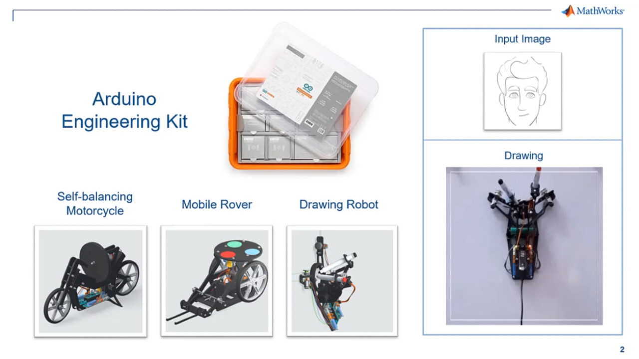
The Arduino Engineering Kit is an initiative by MathWorks® and Arduino®, which provides hands-on experience in building three engineering projects using MATLAB®, Simulink®, and Arduino hardware: self-balancing motorcycle, mobile rover, and drawing robot. The kit has complete documentation and project files containing the code to guide you from start to finish.
In this video series, learn the steps needed to implement the drawing robot. The project contains MATLAB live scripts for seven tasks (tasks 1–7) that are required to configure and run the drawing robot to replicate an image provided through a file or webcam.
This video series has three parts:
- Part 1: Overview of the Arduino Engineering Kit and the Drawing Robot
- Part 2: Tasks 1–4, control the hardware, servo and DC motors, convert motor inputs into cartesian coordinates, test the bot by moving it to a specific position, and define drawing boundaries
- Part 3: Tasks 5–7, show the workflow that lets you convert the input image into motor commands and draw the image on the drawing area
Published: 3 Sep 2021
Hello there. I am Abhishek, an engineer at MathWorks. Today, we are going to see how we can build a drawing robot using Arduino Engineering Kit.
The Arduino Engineering Kit is an initiative by MathWorks and Arduino which provides hands-on experience in building three engineering projects, which are self-balancing motorcycle, mobile rover, and the drawing robot. Through these projects, one gets to learn about MATLAB, Simulink, and Arduino.
In this video series, we'll focus on making drawing robot from scratch. By the end of this video series, you will implement a drawing robot that will draw an image for you on a whiteboard, just like the one shown here. Along with the Arduino Engineering Kit, we have provided you with the project files which are essentially a series of task files that will guide you from start to end. Let's now briefly see what we learn in each of these tasks.
In task one, we'll first connect Arduino with MATLAB. Then in the same task, we'll control the servo and the DC motors. The servo will help us turn on or off the marker. And we will use the DC motors to move the drawing robot on the whiteboard.
Once we are done with the basic control, in tasks two, we'll move the drawing robot by giving low-level commands to the motors. And we'll convert those motor inputs into Cartesian coordinates.
Once it is done, in task three, we'll give specific commands to the drawing robot in which we will provide the commands to move to a particular location on the whiteboard. Doing this will ensure the drawing robot is in proper order. Next, in task four, we'll define the drawing boundaries, ensuring that the bot won't fall off the whiteboard or go too near the edges.
Then, in the final set of tasks-- that is, tasks five, six, and seven-- we'll go through a workflow that will allow us to convert the input image into the motor commands. These tasks will involve some basic image processing and some value conversion, which we will be discussing in detail in the upcoming videos.
Congratulations. You have successfully completed the first part of this video series. I will see you in the following video in which we will go through tasks one to four.


Seleccione un país/idioma
Seleccione un país/idioma para obtener contenido traducido, si está disponible, y ver eventos y ofertas de productos y servicios locales. Según su ubicación geográfica, recomendamos que seleccione: United States.
También puede seleccionar uno de estos países/idiomas:
América
- América Latina (Español)
- Canada (English)
- United States (English)
Europa
- Belgium (English)
- Denmark (English)
- Deutschland (Deutsch)
- España (Español)
- Finland (English)
- France (Français)
- Ireland (English)
- Italia (Italiano)
- Luxembourg (English)
- Netherlands (English)
- Norway (English)
- Österreich (Deutsch)
- Portugal (English)
- Sweden (English)
- Switzerland
- United Kingdom (English)