Clean Technologies Power Electric 3-Wheelers: Last Mile Delivery of E-Vehicles Made in India for India
Prathamesh Patki, Altigreen
Over 5 lakh people lose their lives every year in India due to poor air quality from road transportation. In 2019, 21 of the 30 most polluted cities in the world were in India!
Founded in 2013 and based in Bengaluru, Altigreen designs, engineers, and produces 3-wheeled electric vehicles using proprietary and indigenously built technologies. Altigreen‘s Made in India/Made for India products are specifically designed for the environment, road conditions, and driving behaviors in India. Altigreen’s product offerings stand on four strong pillars: longest range, largest volumetric capacity, highest ground clearance, and greatest torque.
All components, including the motor, motor controller, power electronics converters, telematics/IoT, gearbox, battery, and BMS, are designed and manufactured in our 3 lakh square foot facility in Malur, Karnataka.
Altigreen uses MATLAB® and Simulink® products for its system level simulations and software design, and Embedded Coder® for development. In this session, learn how using MATLAB and Simulink has helped us solve specific technical challenges related to component sizing, BMS design, and more—and reduce the time-to-market for our products.
Published: 11 Dec 2023
Good afternoon, everyone. So as we mentioned, I'm Prathamesh. I'm from Altigreen. I've been working here since 2013. I take care of the Embedded Softwares and Control Department since the beginning. OK. So I'll just start with why Altigreen was started. So basically, there are annually about 10 million air quality related deaths globally. And also as per 2022, 39 of the 50 most polluted cities globally are in India.
So that was the purpose basically why Altigreen was started to do something for pollution problem, is what I would say. And then how are we doing it? It's by engineering-first approach. So we are trying to solve the problem in engineering way to have measured solutions or knowing the requirements of the customers. And based on that, customers have been-- by that I mean the users, and give solutions as per that.
And the other important point, I think, is we are working on building EV technology in India in addition to make in India. So that is also important for solving that problem that we are trying to do. And so what are we doing for that? So right now, we are doing it by-- so we are addressing the global need for EV transition by making three-wheelers at this point in cargo and passenger mobility applications.
And we are targeting the short- and medium-haul transportation in emerging markets. So this is what is are currently. Before this when we started, the same problem we were trying to solve by hybridization. So in the next slide, I will just mention overall about our journey. So in 2011, actually, we started by looking at a lot of Indian drive cycles to know what are the driving patterns, what is the power, the actual power requirements of the vehicles? So that's what was started in 2011.
And 2013 is when formerly Altigreen was started. And that we started with this manufacturing of retrofit hybridization kits. So we were trying to convert the already the ICE vehicles, which were there on road to hybridize them by putting a hybrid kit externally. So it was with an electric motor generator. So that was our patented technology of a dual motor of an induction motor plus PMG. So we did it in 2013. We did it for four different models, certified it. We got into production. We had several vehicles with the hybrid running into it for a couple of years.
By 2016, actually, we were working with OEMs for hybrid technology, as well as we started getting a lot of interest from other OEMs to provide powertrains for their specific requirements. Because, anyways, we were trying to create expertise in the motor controllers and all. So that's how we started working with a lot of other OEMs, we got to know more about the requirements of the system at that point of time.
Plus that was the time when BS4 to BS6 transition was on the road. That's why a lot of OEMs were looking at ways to reduce the emissions and all. And so we worked with other three-wheelers, four-wheeler as well as tractor manufacturers. So at that time is when we actually changed our route to full electrification based on the fame subsidies and overall conducive environment for full electric with lithium ion packs rather than hybridization.
Because that's what we thought overall the Indian environment was getting into electrification environment was getting into. So that's where we started making powertrains for electric vehicles. And 2018, we displayed our powertrain in Delhi Auto Expo. That's when we got very good response at that point of time. And then eventually, we did a retrofit of a three-wheeler powertrain in a [INAUDIBLE] vehicle.
And then later we decided that since we have the powertrain, we'll just build a vehicle around that. And from 2021, we started the production of our three-wheeler cargos. 2022, around 1,000 plus vehicles were there on the road with dealership networks and all starting. 2023, actually, we moved to a bigger manufacturing plant and further scale-up started. So future, again, will continue probably in four-wheeler cargo and passenger segments.
OK. So we started as a startup. So basically, these were the challenges, I would say, that we were facing. So we had limited resources. We wanted to have a shorter time-to-market of our products. There was scarcity of skilled manpower for implementing complex algorithm for motor controls and overall vehicle controls. There was a need for combined knowledge of systems as well as target-level implementation.
Because eventually, in case of motor controls and all, so there is a different kind of expertise required to understand electrical motors. And that is a separate expertise. And then actually implementing controller on a target embedded environment is a separate entity. So we wanted to have an architecture in place for software to be person-independent. There was a need for strong testing and validation process integrated with the development.
We wanted EV components to be EMI-EMC compliant. So that is also one of the major requirements in EVs. And then we wanted to have data analysis method to improve on the system. We keep looking at data, see in what way we can push it back. Use that information to improve on our systems. And we wanted to make, of course, products for the Indian market. So they had to be with a price point suitable for the Indian market but no compromise on quality.
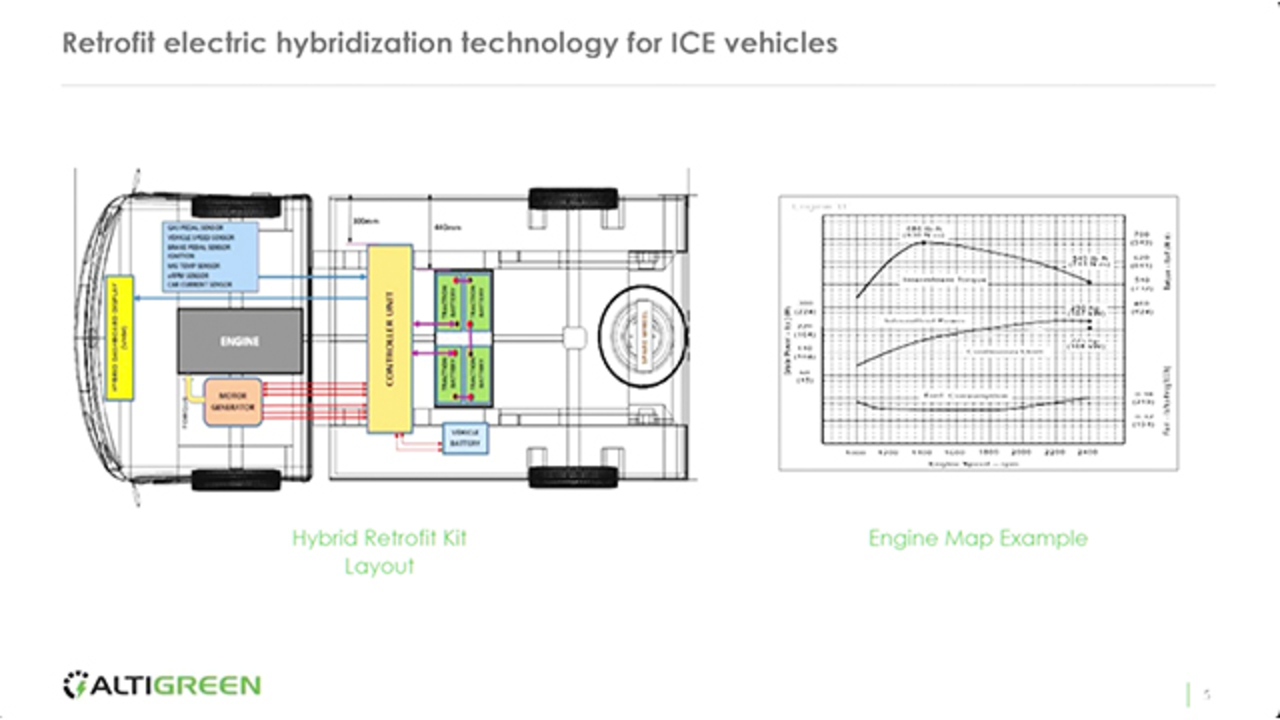
So since the beginning, we started using MathWorks tools. And I would say per in some way or the other, it helped in overcoming these challenges. So quickly, I'll just go through the initial hybrid technology, what we used to have. So there was a motor generator that we replaced the alternator with a machine with its controller and the battery pack. Since alternator was replaced, the 12 volts of vehicle battery had to be charged. So that also, we were charging with a DC-DC through our controller.
There was a display and telematics unit to look at the data. And we were tapping into some of the sensors to make decisions. So that is the overall layout of the kit. On the right side, I have just mentioned a simple engine map example. So there, you see that is the ICE engine map example. There is a torque power and fuel consumption.
So for hybrid kids, we use Matlab for development, simulation, as well as data analysis. So we had simulation models with engine map as well as the electric motor performance. So both were there in the simulation models. And we used to run them to find out what was the optimum pulley ratio, and what would be the optimum assist region scheme to give us the best performance on a particular drive cycle?
So drive cycles is what we use to give as an input, work with different schemes and look at what kind of impact it has in case of better mileage. So this pulley ratio, since alternator was replaced, so it was connected to the engine through a pulley. So that is what is that pulley ratio. So we used to do a lot of data blocks, drive summary analysis. And then our production code generation, we did with Embedded Coder.
So this is just an example of a real-world drive of a vehicle. So on the top right, we see the torque demand. Positives are motoring. Negative is regeneration. So that's what is shown in the second plot of the current. So positive current is discharged. Negative current is charging from the motor. This is the motor speed, which will be similar to engine speed because that is what it is attached to.
This is the PMG current and the voltage of the lead-acid battery that we were using. So basically, we were not using any external energy source. We were not charging the batteries externally. Batteries were being charged during drive by during the accelerations and all. And that energy is what was used for acceleration. So that's why we will see the SOC plot, where we try to remain in a band. We use the energy, try to capture it. That's how it used to cycle. And the last two plots are related to 12-volt battery charging.
So this was just for earlier case. I wanted to mention technology perspective, what it was. So this is about the full-electric drivetrain components that we develop. So basically at present, almost all the components that go into-- drivetrain components that go to Altigreen vehicles are designed and developed by Altigreen. So it includes-- so that side is overall layout of these components in a three-wheeler vehicle.
So we have motor-- so I don't know if I can get a pointer, otherwise. So there is a motor. Close to that-- maybe I'll just show-- so there is a motor here. So there is a motor controller DC-DC converter gearbox, display. And the telematics is part of display. And that is the web app for data monitoring analysis. So let's go to-- OK, let's go to what are the requirements for designing an electric vehicle?
So from our perspective, the main requirement was we wanted to make sure that the vehicle is comparable to an ICE variant in terms of performance. We didn't want it to-- performance-wise, we didn't want it to be secondary to ICE variant because customers' perspective, especially in three-wheeler cargo segment, performance is extremely important for them because they need to carry a lot of load.
So that was our main requirement. Then the typical other requirements for EV design is what gradeability, what in degrees the vehicle should be able to achieve, what would be the curb weight of the vehicle? What is the gross vehicle weight of the vehicle? So gross vehicle weight is the additional payload that it can carry is what is considered in gross vehicle weight.
Then what would be the acceleration and de-acceleration in meter per second squared? What is the maximum speed in kmph so that it can achieve in loaded condition? What would be the energy consumption in watt hour per kilometers? And what is the-- or what can be the range in kilometers that we will get? So this is our simulation model for component sizing, I would say. So for that, so this is the model that we use to use, or VRUP.
So as an input, we can give several drive cycles. So they can be IDC-based, IDC, MIDC, those kinds of cycles, some real-world data. Or it can even be a wide open throttle. For a wide open throttle, what kind of performance we will get? Next is the driver module. Then is the vehicle controller module, drivetrain, and the actual vehicle. So eventually, the velocity from actual vehicle model is fed back to the driver. And it tries to follow the input drive cycle. So that's how the models are set up.
So on the right side, I'm mentioning, so what are the different parameters that we can configure? So from the vehicle side, we can have speed profile, mass of the vehicle, radius, wheel radius, the gear ratio, what kind of gradient it can do, and the vehicle dynamics parameters. So that could be BCE-related parameters or rolling resistance and that kind of model.
From the battery perspective, we can have SOC capacity voltage. From the motor and controller perspective, it will be the efficiency maps of the motor. What is the peak and continuous torque of the motor? And what will be the peak and continuous power-- peak time and max speed? So these are the parameters that we can control on this model. So typically, when we are trying to cite something, what we will do is we will keep one as a variable parameter, others as fixed. Then we run the models and try to see what kind of effect it has.
So down these two graphs, what we see is the motoring power is what is limited on the second graph, what kind of effect it has on the speed profile. So we can see the acceleration was affected. So that way, we can have everything else fixed and then check for different gradients, what is the max speed that it can achieve? So these kinds of things, we can do. Plus even from the battery perspective, we can know what would be the energy consumption, what would be the range that will get for a specific heat capacity of battery.
One more important thing is the green block that we see here. So that is the vehicle control block, which actually goes into our vehicles. So in the target environment is what we place it as it is. So here, for example, we see that-- so there is a positive power, and there is a negative power here shown. So it is initially when battery was full, actually there was no region. Then we started some amount of region, then full region. So that all of those scenarios, we can actually check in the simulated environment first. And then in the real vehicle, it's pretty much the same algorithms that go.
So after the vehicle, I'll just cover something about the motor controls requirement. So for designing a motor controller, so what we work is induction motor is what we have been working on. So we had a mathematical model of induction motor, then field-oriented controls implement-- the controller implementation is what is required. Then we wanted the controller to be target deployable on the actual embedded target.
And so we wanted to match the controller timings to the target execution. So simulation timings and controller and the target execution timings had to match based on the microcontroller, and what are the execution rates that we can get through it? And so one more thing we wanted to do was we wanted to combine the motor controller as well as vehicle controller in a single physical unit. So that we can have some saving on the physical component cost.
So we had a simulation model running initially. So on the left block, we have the torque and speed input. The green is the FOC motor controller algorithm. Again, the green block is something that eventually goes into our final target. And on the right side, we have mathematical model of induction motor. So this model was something that was made by an expert in motor and motor controller. He did not know much about on the target environment what is required.
So that is what we used. So this was being executed in virtual simulated environment. It was being executed at a very fast rate. That was mainly to simulate the real motor phase currents and all, which is part of the motor model. So what we started doing was-- so first thing we did was we actually slowed down the control model so that it is comparable to what we can do on the target was one. And second was as per the motor controls, the execution of a motor controller has to be as per the Nyquist criteria.
So if that PWM we are working for the phase generation is whatever hertz, kilohertz it will be, so this has to be at least twice of that frequency. So typically for motor controller, that's why motor controllers have to execute extremely fast to generate the sinusoidal waveform through PWM modulation. So first, as a first step, we slowed it down so that it is as per the Nyquist criteria.
But as I had mentioned that we wanted to put in additional, I would say, application into this physical controller, we broke it further down into submodels of the motor controllers for which models are extremely necessary to execute at Nyquist criteria and faster rate, and which we can actually slow it down. So that way, we were able to reduce that or use that execution bandwidth to push in our vehicle controller in the same physical target.
So on the bottom, we see just for information I have shown, the-- so our controller worked in the torque mode. So this is the speed. The second yellow graph is the speed ramp-up. That is the Id-Iq current. And on the right side, it is the theta and modulation index. Now the advantage here of doing this was with every change that we were doing, timing-related change that we were doing in the controller, we were actually trying to check that it will not affect the performance per se of the simulation.
So a lot of that, we were able to do in the simulated environment itself. And then when we were quite confident on the simulator environment, we spent quite less amount of time on the real controller and real motor on the bench. OK, so that is about the motoring portion. So the third example that I want to give is about BMS. So again, so we have our own BMS and our batteries.
So again, from our own BMS perspective, our requirement was to integrate device drivers, where it was a lot of manual coding initially when device drivers were made for the BMS to communicate with the BMS IC. And we wanted them to be integrated with model-based algorithms. Then filtering of signals for EMI compliance. Of course, that was something that we were looking at. Then modules to be unit testable.
The BMS, again, we wanted it to be target deployable directly from model to a target. And so one of the important requirement for us was from the SOC estimate perspective. Because range anxiety is one of the biggest concerns for users for going into EV. Because definitely as electric vehicles range-wise, we cannot compare it with petrol or diesel vehicles. That is first. And second is the charging time. The filling up time is also much higher than petrol and diesel vehicles.
So this is with whatever limitations that we have to live with those limitations. But we have to just make sure that the drivers, they get to know the exact state of charge of the battery-- how much they will be able to drive, they should know exactly. So for that, initially in our BMS, we were using Coulomb counting-based SOC estimation with some-- so typically, that's what most-- they do. I think there are some correction at the lower end and higher end of SOC based on voltages.
So we decided to go a step further and implement an extended Kalman-based SOC estimation block. So we had a lot of real-world data. So this at the bottom, there is a real-world full discharge cycle on roads. So there is the voltage. Those are the charge-discharge currents. And that is from 100% to whatever full discharge point. So we fed a lot of these inputs to the model, basically, to tune the-- so for Kalman gains. Kalman gains, we have to tune so that it response in the corrections are made in a better way. So that tuning is important.
So that's what we see. On the right side, I've kept some plots, where in the black color line that we see, that is the real-world Coulomb counting SOC that we were getting. So we see actually at some about 5% or 6% itself, the battery had given up. So of course, driver would not have been happy because at 5% itself, he understood that the vehicle has stopped. With Coulomb counting, that is what would have happened.
So we fed this data to the model, tuned it, and then the yellow color that we see is the Coulomb-counting from the simulation model. And the green color that we see is the EKF-based SOC estimate. So we see that at the end, it is actually very gradually coming down slowly until 0% this way. So it will for sure give a better indication to the driver to know that when the vehicle is going to stop.
So same thing, I've just executed that the second graph wherein suppose if I had started at a totally wrong estimate, then what happens? So again, we see the Coulomb-counting actually was fully-- I mean, it was nowhere near. And then the green line, Kalman line, we see that gradually still it is giving quite realistic kind of SOC estimate to the driver. Because there are no sudden jumps, or there is no sudden drops.
Because typically, any sudden drops from the driver, he will not have any confidence on the SOC. So though it might not be right at that point, but still it is a gradual decrease. So that at least in the end, he knows that now he is almost-- the battery has gone out of the juice. OK, so this is what I wanted to show in what way using model, we were able to-- so now, again, this green block is something that is actually executing our BMS targets today.
OK, so these are some of the advantages, again, what we saw by working with these tools. So one is, again, vehicle controller and motor controller. We were able to combine them in a single physical controller. Then up to 90% of model-based development we are doing with a small hand-coding. Mainly driver-related is what at some places we still do hand-coding.
So then in our case, the manual hand code is integrated with the models and not the other way around. And then hex files are generated directly by building the model. That's how our production code is generated. So modeling and simulation, code generation to target deployment. Again, because of all of this from thought to real world or the time was significantly reduced. So that's what our time-to-market we were able to improve significantly.
Plus any problems that we see in the field, and if we are solving those, we can do it much quickly-- first in the simulated environment, and then back to the target environment. And for the last point, we were able to do quick itera-- so that's what I mentioned-- quick iteration between simulation, target, real-world data back into simulations. And that kind of tuning, we are able to do.
So this is just my closing slides, where we-- so this is our production plant at Malur. And those are kind of brand centers that are being-- in 30 plus cities, we have our dealer networks. And these are the models. So one is Altigreen neEV. That's a slow-charging model with about 120 kilometers range. And the other one is neEV-Tez, which is a fast-charging model. So it gives around-- it's 80 kilometers range. And then it can be charged in 15 minutes. So that is with one of our partners, partner battery and charger packs. OK, thank you. That's it.
Featured Product
Simscape Electrical


Seleccione un país/idioma
Seleccione un país/idioma para obtener contenido traducido, si está disponible, y ver eventos y ofertas de productos y servicios locales. Según su ubicación geográfica, recomendamos que seleccione: United States.
También puede seleccionar uno de estos países/idiomas:
América
- América Latina (Español)
- Canada (English)
- United States (English)
Europa
- Belgium (English)
- Denmark (English)
- Deutschland (Deutsch)
- España (Español)
- Finland (English)
- France (Français)
- Ireland (English)
- Italia (Italiano)
- Luxembourg (English)
- Netherlands (English)
- Norway (English)
- Österreich (Deutsch)
- Portugal (English)
- Sweden (English)
- Switzerland
- United Kingdom (English)