Algorithm Export Demonstration | Deploy C Code to STM32 Nucleo Using Embedded Coder
From the series: Deploy C Code to STM32 Nucleo Using Embedded Coder
Learn how to generate customizable C code for a Simulink® algorithm model, then include that C code in a hand code project using STM32 CubeMX and IAR Embedded Workbench for ARM, and finally compile and run it on the Nucleo.
Published: 12 Sep 2021
In the first example, we saw how we could use support packages to automatically generate not only the algorithm that we want to export, but also the drivers, and directly interfaced with the board. Now, this workflow is really useful for a lot of prototyping applications, but sometimes you want to have more control over the algorithms, and the driver interfaces. And so there's also the ability to just export the algorithm.
This is a very common workflow where you're actually converting the Simulink components into just standalone C code. And then you can take that into another IDE and compile that, and actually incorporate it in to your larger software project. So let's take a look at how that's done.
In this example, we're going to walk through building a Simulink model from scratch, configuring that for code generation, exporting that out as C code, and then taking that over to our target IDE. In this case, because we're targeting the micro ARM processor, and we're going to be using the IAR Embedded Workbench IDE to actually do the compilation, and deploy. So we'll go through this step by step.
OK, let's hop over to Simulink can start to build this algorithm. The algorithm we're actually going to build in this case, is going to be an algorithm that's going to modify the time delay as we switch LED pins on and off. So we're essentially going to slow down and speed them up, using a sinusoidal duty cycle adjustment. So this is the simple model we're going to build.
So let's go over to Simulink and see how we can actually do this. So I'm going to build this model from scratch. Launch Simulink here, create model, and from here we can start to actually put this model together. And the way we're going to do that is we're actually going to just grab the components we need, the sine block, gain, maybe for some quick prototyping I'll look at the scope.
And just to kind of get started, I'm actually going to just adjust these parameters to something that I know. Put the LED to blink at a reasonable rate and values. So bias is 0.25, frequency of 0.1, and then in my sample time, in this case is going to be one second. We'll have this execute every second. You'll notice that this figure has changed, basically demonstrating this is now a discrete time signal.
I'm also going to scale this by 1,000 just to kind of add some additional effects here. Make this slightly more interesting. Then we can look at the scope here and see the results of this algorithm. So we can simulate it in desktop and observe what the results are. OK.
And right now we can see like over a span of 10 seconds the rate's going to go up over time. It's kind of maybe not enough time to see, so let's do 100 seconds. And now we can see the sinusoidal right? So the duty cycle should be in the middle to start, go higher, and then go lower. So we should see some frequency changes in the duty cycle.
Now, right now this model isn't really configured to be used as an algorithm for export for a couple of different reasons. Primarily, first of all, the scope is just visualization for stimulation, for desktop simulation. And so what we want to do is we want to actually grab an output port here, to tell the co-generation engine when we generate code here, that this is actually going to be an algorithm output. And this is going to be something that we can then integrate in.
Correspondingly, if we wanted to have an input, we could grab an input port from the sources library as well. And I'm going to call this wait time. And that's going to be our value there. And I can now go ahead and get rid of that slope-- or that scope. Now, when you first create a Simulink model from scratch there's a few things that you're going to need to actually set up to do code generation.
So in the previous example, we selected a hardware support package that set up the model. In this case, since we're just exploiting an algorithm the easiest way to do this is go up to apps, and then go into embedded coder.
This will switch the target to embedded code generation, and maybe before I generate code I'm going to give this model a name. We'll overwrite my old one, sineRateAlgo.
So this is going to be the function name, the model name. And now I can actually kind of start the process. Now, you can set all of this up from scratch, but if you are new to this I would recommend using the quick start. This is going to help you kind set up the model really quickly for code generation.
So we're going to select this model. You could choose a subsystem of interest. We're generating C code in this case. This will kind of look at the model, what the blocks are that we have. It will give us some information here. And in this case, what we want to do is select the device vendor that we know we're working with. So we know we're working with an ARM device. And in this case, it's a Cortex-M.
And you'll notice the main thing this is changing is actually the bit definitions for different data types. So if you have a processor class that's not listed here you can always go into custom processor. Now you're going to have to fill out all of these fields yourself, right?
Just a little more work on your end to get the code generation. You can select the efficiency, or the process you want to take there. And this is now showing us all of the setting changes that this quick start guide did for us automatically.
So you can see there's a lot of stuff going on here. I've run into many cases where customers generate code for the first time, and they just use a default model, and they see a lot of weird stuff in there. And oftentimes it's because you're generating code that has debugging features, and stuff that you use in simulation.
And Simulink's code generation tools try to replicate exactly what you have. So if you're generating code for targets, I really recommend using this embedded code or quickstart. It'll get your code in a much better state immediately.
And once we've done that it actually went through and generated code for the model as well. So you'll see here that we have the original model, and now we have the generated code for this algorithm. OK. And so you can see this is the algorithm. Most of this is just going to be calculating a sinusoidal waveform. And then incrementing with the clock in time.
From here if you wanted to say, modify this algorithm and generate code again, you can select this button here. There is the option to just generate code. This is very useful if you know you're going to be taking this generated code into a different development environment immediately. OK. Now if we go and take a look.
When we generated the code that gets generated into the model name underscore ERT Folder here. And it has a few different things. It's got the make files, so if we wanted to compile it. But really there's a couple of key files here the dot C, algorithm.c, algorithm.h, and then there's this example main file. This one I always recommend new people for code generation take a look at. This is just an example to show how you can start to interface the generated code into your software.
And so really what you'll see here is the main pieces of the code, which are the sine rate algo underscore step function. And then the sine rate algo underscore initialize function. So one is going to initialize any kind of initial state, so you can think of integrators if they have an initial condition, that's going to be defined in this initialize function. The code that gets executed say in the Simulink solver step, all of that's going to be as part of this step.
Now lastly, if you want to actually make this a little easier, what I recommend doing is actually loading the build into a file, here. This gets generated automatically. And then we have a function called packNGo, and what this actually will do, and this is something I use all the time, is-- there's a lot of files in here, it can be pretty easy to get lost.
It'll package up all of the files. I like to use this flat hierarchy, makes things even easier. Into a zip folder here that you can then take over to your IDE. So you're not having to weed through and select the files. If there's any dependencies on other files, you'll see here there's one called the rtwtypes.h, the header file.
It'll package those up as well. And if you're curious what this one actually is, when we did that hardware selection in the quickstart, this sets up the mapping for that. So if down the road you say, generate the same algorithm but for a different processor class that has different definitions here, the rtwtypes would be different.
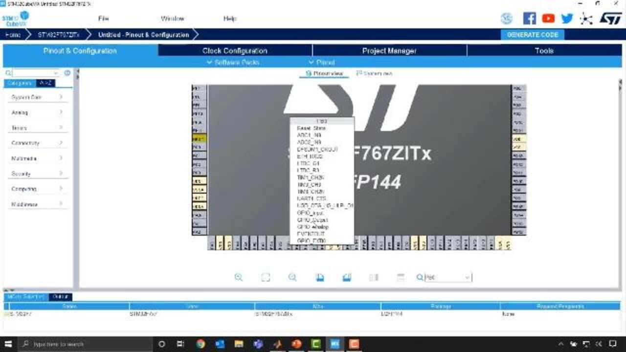
OK, now that we've actually generated the algorithm code we can do the rest of the work in Third Party ID. We're going to start this process using STM 32 Kubernetes. This is going to help us build the structure of the code to work with the nucleo processor. Where we're going to start is we're going to pick the board that we're working, with the chip we're working with. And in particular, the one we're looking for is the STM32F767.
And in particular the I, and you'll see there's only one that shows up, that's the one that we have. Once we select that we can start the project. And once the project starts you get this pin layout. What we want to do is configure the specific pins that we're working with to be in output mode.
And so in particular, we want to just select the pins that are the LED connected pin. And you could look this up in the documentation. The way we can find them, I know it's pins 0, 7 and 14 in this case. I can search for it, it highlights it down here.
And what I can do is select that, and then you can see you can configure what you want to do with this pin. In my particular case, I'm going to configure that as an output. We can do that for the other two pins that we're interested in, PB7, which is up here. We can make that also an output. And then PB14, which I believe is down here somewhere. PB14.
So I configured those all as outputs. Once I've done that we can go to the clock configuration page. This lets you set up some additional things, again, this is kind of like another way of code generation. This is the Kubernetes form of it. And what we're going to do is just change the clock creating here. I think the default here is 16, we're going to change it to 216.
And then once we do that, we can hit Return and let this calculate a solution for all the other clock values. And once it's done with that we are good. We can then go to the project manager tag, give this project name. Example algorithm we'll just put this in the ST folder.
And the last thing is we just want to make sure that we're selecting the IDE of interest. In this case, we're using EWARM. You can see there's others as well. And then from there, once we're done, we can save this. Save project. Once we've saved it we can generate the code, and this is going to create the project. And then we can open that up.
All right, so now we're in the embedded Workbench platform, and this is where we can start to actually modify the main file. So by expanding out the application here we can get into our main.c. If you think back to the generated code that we had from Simulink, we had that ERT main example file, and so this now is a main.c that's been created for us, that we can now modify, right? And so you can see there's little sections we can put our code.
There's a init function for the specific processor, to configuring the clock, and this is all defined by the settings we configured in the Kubernetes platform. And then down here, you'll see there's a while loop. So this is going to be the code that executes along on that clock cycle.
Now what we could start to do is just put in some example code here. I have this in my clipboard, which is going to just trigger these pins that we've configured 0, 7, and 14. And we're going to trigger them on and off with a fixed delay rate of 500. You could then make this, and then deploy it to the board. This is of course now going to be fixed, right? We're not actually going to have that sinusoidal variance, right? We just kind of hard coded this.
All right, now that we have a hand code project set up here, let's go and grab our algorithm that we exported from Simulink and incorporate it in. Now, the first thing we need to do is add the semi Simulink to this IDE. So let's go back to MATLAB. Let's copy this zip folder, so do the Control C.
And now I'm going to go into my directory where I have this project, where we're going to go into the driver's folder. And we can just create, like another folder in here called Simulink for example. Go into this folder, paste my zip file, I can just extract it. And actually the main files that I need are going to be the .h, the headers. And then the algorithm.c.
We don't need that example main, and these other files are just for reference. So I'm going to paste these into this folder, and I can go ahead and get rid of those others. So we have these components here. Let's go back to the IDE here. And so what we'll do is we can now go into our drivers here, and then add a group, and we can call this group Simulink just to kind of keep consistent here.
And when we've added that Simulink group now we can go ahead and add files. So we'll right click again, Add Files. And again I need to go back to that folder, which is an ST example algorithm, drivers simulator. And what I can now do is select that sine rate algorithm.c file. That's going to import that in. And once we've done that, we should be good to go here.
Then what we need to do is add that folder to our path, and so the way that we can do that is we can just go up to the project name, go to Options, and then go to the C/C++ Compiler. Go to preprocessor. And let's add a Simulink header file to the path here. So quick to add. Let's select that Simulink folder. Select it. OK. OK, selected that folder.
Now that we've added the custom code, or the custom algorithm into the IDE here we can start to add the software in the actual code. This code is basically the infrastructure, and that was pre-created for us. And now we just need to reference the algorithm that we've exported. So there's a couple of things we need to do, of course, we need to include the header files that were generated. And so what we'll do is include those. And first one, of course, is sine rate algo, that header file. The other one, of course, is going to be that RTW type, so what we need to grab there is rtwtypes.h.
So now we've included both of those header files. The next thing we need to do is, of course, to add some software into the main function. As you recall, there was kind of two main pieces of the generated algorithm code. There's the init function and then the step function. So when we start this main function here you'll notice that this software has an init.
This is going to reset all the peripherals and whatnot. We also want to make sure that we initialize the algorithm that we've generated from Simulink, right? So we can add the code here. So sineRateAlgo, and you'll notice here we have the initialize. We're just going to call that. And once we've done that, we'll see we have some more initialize, and then down here we enter into the while loop.
So this is going to be the main code execution. We initially had some software here to trigger these pins at a rate of 500 milliseconds. So what we can do is now add our algorithm that's going to adjust this duty cycle with that sine rate. So sine rate step. We'll just call that every time. And lastly, we need to actually grab the value that's being output here. And so if we go into the code that we generated, and we can take a look. And basically the output port here was called wait time. That was just the naming scheme that we used in our Simulink model.
So the output port, whatever you've named it, that's going to be added into the code. And so the structure here rtY, that's going to be basically all of the outputs of the algorithm. In this case, we only have one, so it's rtY.WaitTime. And so this is going to be the numerical value that's the output of the sinusoidal wave function. So we can copy that and instead of hard coding the 500 in, we can use that RT wait time.
Once we have this all set up we should be able to try actually using this code. And so what we'll do is we'll go ahead and try to make the code. You'll see we have no errors, built successful. And then we can actually get this onto the ST micro nuclear processor here. So we deploy it, everything's set up, and then we can go ahead and hit go. This is going to start the code. And what you should see now is the LEDs are blinking, and I'll kind of just hold this here.
As time kind of goes on they're going to slow down, and then eventually they should start speeding up. So the duty cycle here of these LEDs is being controlled by that sine rate algorithm that we created in Simulink. And so really the key was to kind of just interface with that algorithm exported from Simulink. Bring that code into the external ID of interest, in this case IAR Embedded Workbench. Make sure that we had everything on the path, and then interface that code. And so we can see that this is now running.
All right, to wrap up, we saw how we could take algorithms that we've created in Simulink, and generate code, and deploy them to hardware in two different ways. The first approach was to essentially use a hardware support package which simplified the process, allowed us to directly go to the board, automatically takes care of the compilation process, interfacing with the drivers, and all of that.
And so when a hardware support package is available this can significantly simplify the generation process. The other approach we took a look at is the more customizable approach, which is the algorithm export approach. And so this uses embedded code to basically take a portion of your Simulink model, could be an algorithm, could be deep learning algorithms, could be any routine that you've created.
Converts that to ANSI standard C code, that we can then take to another compiler, integrate into a larger project, interface with drivers directly in that third party ID, and compile to a processor. So depending on if you need additional flexibility, or have some existing code, or a processor, or if you're dealing with say, a new processor where there's no hardware support package, you can still export that algorithm and interface directly.

Featured Product
Embedded Coder
Up Next:


Related Videos:


Seleccione un país/idioma
Seleccione un país/idioma para obtener contenido traducido, si está disponible, y ver eventos y ofertas de productos y servicios locales. Según su ubicación geográfica, recomendamos que seleccione: United States.
También puede seleccionar uno de estos países/idiomas:
América
- América Latina (Español)
- Canada (English)
- United States (English)
Europa
- Belgium (English)
- Denmark (English)
- Deutschland (Deutsch)
- España (Español)
- Finland (English)
- France (Français)
- Ireland (English)
- Italia (Italiano)
- Luxembourg (English)
- Netherlands (English)
- Norway (English)
- Österreich (Deutsch)
- Portugal (English)
- Sweden (English)
- Switzerland
- United Kingdom (English)