Rapid Prototyping Demonstration | Deploy C Code to STM32 Nucleo Using Embedded Coder
From the series: Deploy C Code to STM32 Nucleo Using Embedded Coder
Discover how to quickly deploy, test, and refine algorithms with rapid prototyping. Learn how to create a simple Simulink® model, configure it for the ST Nucleo, and then deploy and run it on the Nucleo with one click.
Published: 12 Sep 2021
All right, for our first example we're going to use the HelloWorld hardware, which is blinking an LED. The ST Micro Nucleo board has a few LEDs that are accessible here that are specific pins. And so what we're going to do is basically construct a Simulink model, set it up so that we can generate code to blink an LED on this development board, and we're going to do that using the support package approach.
So before you are able to try any of this, the first thing you need to do is actually download a support package. So depending on the hardware you're trying to target, you need to download that hardware support package. From MATLAB here you can actually do that from our add on Explorer. Go in here and you can search for the package of interest. So for example, in this case we're working with the ST Nucleo processor. You'll see here I found the support package for that. I can select that, and then I already have it installed, but you would see an install button here.
You could install it and then go through the setup process. That will not only install the support package, but any kind of compiler, or secondary tools that are needed. Once you have that set up, let's go ahead and now build a Simulink model to actually blink this LED. So what we'll do is we'll go to Simulink. We'll actually just start from a blank model here. So we're going to start fully from scratch. And so what you can do is you could start adding blocks in here. You open up the Simulink library, we have kind of the base Simulink blocks.
After installing a support package-- you'll see I have some other support packages installed here for Texas Instruments, Raspberry Pi. You'll notice here I have my STMicroelectronics library, and here are the blocks that basically are the drivers associated with this board. So again as I mentioned, if we want to control the pins we have digital write, digital read. Now before we start to drag and drop these blocks out into the Simulink model, Simulink is kind of a generic simulation and code generation tool.
And so you can do a lot of different things, you can simulate electrical systems, mechanical systems, you can simulate algorithms, multi-physics, and so it's a very flexible tool. But if you know you're targeting a specific device, it's always good to tell Simulink that you're doing that, and it's going to optimize things for you. And so what you can end up doing is go to our apps tab here, and you'll see, depending on the tools that you have installed, a list of different apps. I will scroll down here to setup to run on hardware, and you'll see here I've got a link here to the support packages as well, but what I want to do is say run on hardware board.
OK. What I can do is now say select the hardware board. This is going to look at the support packages that I have installed and then allow me to select the board that I'm actually working with. And so you'll see I have a list of different tools here. In this case, the actual development board that I have is the Nucleo F767ZI.
So this one right here. We can select that. And you'll notice this, it said under that code generation settings will be changed. So it's basically set up the code generation tool to target this board specifically. And so now we can start to add different blocks to represent blinking the LED. And so what we'll do is we will grab the digital write block. This is going to write a signal to a pin on the board, and then what we want to do is grab some kind of a signal. And so in this case, I'm just going to grab the pulse generator block.
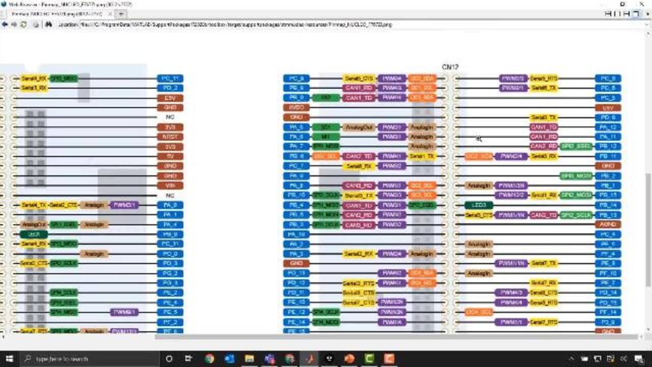
This creates basically a pulse on and off. If we go into this block a lot of these settings are kind of geared for just basic simulation. 10 seconds for on and off is a little bit long for visualization, so I'm going to go ahead and change that to one. And then for my pulse width I'll make it 50, so it's half a second off, half a second on. We've got that set up. Say OK. Nextly, the block itself right now is just default to pin zero. What we need to do is look at what pin we want to actually map this to, and so if I go to our pin map here, this shows us the board itself, and all of the different pins that we have here on our ST microprocessor.
OK, and so what we can do is kind of hunt down our LED. You'll see their serial channel PWM Analogin. And you'll see here LED1 is PB_0. And so what we can do is type in PB_0. And now when we convert this into code this should write this pulse signal onto that pin, and we should see a blinking LED.
Now once we've got all of this set up, what we can do is make sure we're under the Hardware tab. I can expand this out just a little bit. There's a couple of options. We'll come back to this one here in a second, but this button right here is how we actually convert to code. So there's the Build button. This will basically just generate the code and compile it. This is actually-- the second button is actually going to build the code, deploy it directly to the processor using the compiler, and then start that code. So let me go ahead and select that. And let's get the code generation process started.
And I'll open up the diagnostics window so we can see the code-gen process in action. OK. And now this is complete, and we should be able to take a look at the blinking LED. As the code has been compiled and deployed we can take a look at our LED. You'll notice right here our LED is blinking on and off. So we have successfully generated the code and deployed it.
So this is on and off, like we said, half a second on, half a second off. Now the other button up here that we didn't discuss, monitor and tune, what this one will actually allow us to do is actually adjust the code as it's running on the target. So for example, these parameters here, pulse width, or period, if we wanted to adjust the frequency of that PWM waveform we could set this up to basically allow us to tune these on the fly.
And so what we'll do is set this model up to do that process now. So the main thing you want to do is, of course this is set up to do the pulsing of the signal here. What we need to do is also tell the tool how long we want this to run. I'll change it to infinite.
And this uses a technique called external mode. So what we want to do is go into the hardware board settings here, external mode, and we just want to make sure that the serial port is set up correctly. So this is kind of one of those gotchas. And so the way that I can do that, is go to my Device Manager if I'm in Windows, and then go down to my ports.
And we'll see that this ST link virtual COM port for the ST micro board is on COM4. So you can just change this from COM1 to COM4. And now what we can do is hit monitor and tune. So again, this is now going to generate the code, but in addition to the algorithm code to do the blinking LED, what this is going to do is add an additional serial interface bit of code to keep a connection between Simulink and our target device, and allow us to actually adjust parameters on the fly.
So I can open up this code-gen thing we can take a look. So now what we'll see is that this has started model execution on the target. This code is now running. If we look back at the camera we'll see that our LED is blinking again right here, and it's blinking at a rate of on and off of half a second.
Now what I can do is I can go back to my Simulink model. Right now my pulse generator again, is turning on and off every half a second, I can maybe change this to-- we'll see that it's slower. So this allows me to tune things kind of live.


Seleccione un país/idioma
Seleccione un país/idioma para obtener contenido traducido, si está disponible, y ver eventos y ofertas de productos y servicios locales. Según su ubicación geográfica, recomendamos que seleccione: United States.
También puede seleccionar uno de estos países/idiomas:
América
- América Latina (Español)
- Canada (English)
- United States (English)
Europa
- Belgium (English)
- Denmark (English)
- Deutschland (Deutsch)
- España (Español)
- Finland (English)
- France (Français)
- Ireland (English)
- Italia (Italiano)
- Luxembourg (English)
- Netherlands (English)
- Norway (English)
- Österreich (Deutsch)
- Portugal (English)
- Sweden (English)
- Switzerland
- United Kingdom (English)