Developing Autonomous Mining Systems
Overview
Mining companies are increasingly turning to autonomous systems to improve efficiency and productivity, while increasing safety and sustainability. Some examples of these intelligence systems include automated haul trucks and other mobile equipment, robotic automation, and drilling. MATLAB and Simulink provide algorithms and tools to design, simulate, test, and deploy robotics and autonomous systems. In this webinar, you will learn how you can leverage MATLAB and Simulink for autonomous system development workflows, such as:
- Platform design and analysis
- Path planning algorithm designs
- Sensors and simulation environments
About the Presenters
Alex Shin is a Principal Application Engineer at MathWorks. He specializes in helping customers in the area of simulation, verification and automatic code generation, primarily for commercial projects. His recent work includes defining simulation and code generation process and implementation of Model-Based Design tools in large organizations. Mr. Shin received bachelor’s degree from University of New South Wales in mechatronics engineering.
Ruth-Anne Marchant is a Senior Application Engineer specializing in Simulink, and Model-Based Design. Since joining MathWorks in 2015, her focus is on supporting customers adopt Model-Based Design with Simulink. Prior to joining MathWorks, Ruth-Anne worked in the Canadian aerospace industry as a control systems engineer. Ruth-Anne holds a BASc in computer engineering and an MASc in electrical and computer engineering, both from the University of Waterloo, Canada.
Recorded: 2 Sep 2021
Hello, and welcome to this session on developing autonomous systems in mining. I'm Ruth-Anne Marchant, one of the application engineers at MathWorks Australia. And I'm joined by my colleague Alex Shin who is also an application engineer here at earthworks. Alex and I both focused on supporting our customers adopt MATLAB and Simulink based development workflows.
Alex and I have the opportunity to work with a wide range of customers in Australia and New Zealand. And more and more, we're hearing from mining companies who want to do things like incorporate advanced machines and technologies into their systems, use artificial intelligence, big data and IoT, increase connectivity between components and users, and embrace digital transformation in research development and operations.
And these trends are driving what the mine of the future looks like. Companies are developing increasingly autonomous systems working in the mining value chain. These systems are becoming more and more connected, supported by maturing wireless connection technology and IoT. The amount of data collected is growing as our cloud compute and AI technologies which are used to make sense of this data and produce actionable insights.
Cloud computing and AI technologies are also used to improve mining process performance, say through optimization. And plant operators are gaining deeper operational intelligence they use to monitor, update, and adjust processing systems. Now today, we'll focus on developing autonomous systems for mining applications.
Now, speaking with customers working in this space, we hear about some of the challenges that arise when developing autonomous systems. And there are three main challenges we hear about. And they are, so first, the complexity of advanced autonomous algorithms needed. Technologies from perception, planning to control are needed for autonomy.
Second, a need for end to end workflows. An efficient development workflow will minimize the process waste in developing autonomous systems while streamlining the steps from prototype to production. And thirdly, ensuring system quality and reducing risk is a challenge. And MATLAB in Simulink provides solutions to alleviate these challenges.
Though the complexity of autonomous algorithms increase, MATLAB and Simulink provide a robust set of tools and features to help develop your new autonomous applications. MATLAB and Simulink also offer an integrated environment that span your autonomous system development workflows, from ideas, to prototyping, to production. You can design, test, simulate, and deploy your systems without the need to switch tool chains or port your applications to differing environments. And finally, you can evaluate system level design quality through virtual testing in a multidisciplinary development platform, thus ensuring the quality of your autonomous system.
And autonomous systems developers are using MATLAB and Simulink in their development workflows. Here's one example of an autonomous algorithm development: an autonomous braking system. This is an example of Scania You may have seen their trucks driving on our roads. Scania developed their autonomous braking system using MATLAB and Simulink. And here you see videos of this autonomous braking system in action.
This autonomous advanced emergency braking system is capable of fully preventing rear end collisions with moving or stationary vehicles in speeds of up to 100 kilometers an hour. How do they do this? Let's take a look.
So they gathered over 80 terabytes of driving data from vehicle logs and then use MATLAB to visualize this sensor data. And then using this sensor data, they developed sensor fusion algorithms by merging the video and radar data. They then integrated the algorithms with the controller design in Simulink and deploy the algorithms on the vehicle.
But there's more to it than that. With all this data, there was a huge variety in the driving conditions. And this turned out to be a very large verification task. With 80 terabytes of data it was hard to even find the interesting events to test the design. So Scania used machine learning to automatically identify critical events in the data stream. They then simulated these critical events and used the simulation based test results to refine the algorithm and redeploy the updated autonomous algorithms to the ECU.
Let's take a look at another example. This one's from Caterpillar. Caterpillar used MATLAB to develop their big data infrastructure which is used to automatically detect and classify personnel and classify equipment. This autonomous detection and classification system includes collecting data from the field, preprocessing the data, including performing ground truth labeling on the data.
The labeled data is then sent to a database and verified by human. And then it's used to train machine learning algorithms which are then deployed to an embedded device. And Caterpillar developed this infrastructure in MATLAB and were able to speed up design iteration time, reduce manual work via automation, and scale up to support more users and vehicle data.
One of the common threads these two use cases share is that they both use MathWorks tools across their autonomous systems development workflow. Caterpillar leveraged MATLAB to build their autonomous systems all the way through to implementation and deployment. Now MATLAB, if you're not aware, is a development environment and programming language used across a wide range of engineering and science applications. You can use it for things like data analysis, and visualization, and numerical functions, and file inputs and outputs.
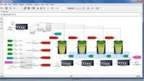
Now Scania our first example leveraged both MATLAB and Simulink through the development workflow. And what a Simulink? Well Simulink is a block diagram environment for modeling and simulating dynamic systems. It has a comprehensive library of blocks which you can use to model multi-domain systems in a single environment.
Now what does a typical workflow look like when developing autonomous systems? Well the graphic on the right is a high level representation of the common capabilities. And these include developing the system of the platform, sensing algorithms, perception algorithms, capabilities for deciding what to do and planning what to do, and then capabilities around taking action. And bringing this all together, there's this element to connect all of these pieces.
I'd like to drill down into what this looks like in the context of autonomous mining systems. And to make this a bit more interesting, we'll use a concrete example. The example system is an autonomous vehicle working at a mine site. The objective is to move mining material from one point to another point autonomously.
Now I recognize not everyone here is developing autonomous vehicles but I use this example to help paint a picture of what capabilities are typically required in an autonomous system and how these capabilities fit together in the bigger picture. And then how you can use a single, integrated environment across these capabilities.
To develop this autonomous system, well, first you need to design and build the physical vehicle. Before the vehicle could move or do anything, it needs sensors, for example, cameras, lidar, radar, IMU or GPS. And it also needs some way to perceive the surrounding environment. So, for example, object detection, localization, sensor fusion, or SLAM.
Now before the vehicle can move, it needs to decide what to do and plan how to do it. And some of these algorithms include things like identifying the trajectory, motion planning, obstacle avoidance. And then, with this information, the vehicle can move its control system. So these are your control algorithms, your logic, say path following, which then feeds commands into the physical system, resulting in movement.
Let's look at these individual components and how MATLAB and Simulink can help. And we'll start with modeling the physical system. There are blocks you can use to design and build the physical system. So common use case for these include exploring custom designs, capturing all the physical effects like faults and nonlinearities, performing abstract and detailed analysis, and testing individual subsystems and system integrations within, say, the vehicle.
Now if you already have the physical system and your tasks focus more on designing or validating control algorithms on the desktop or for hardware in the loop testing, perhaps performing vehicle level analysis, so fuel use battery range, or exploring perhaps standard design, so different architectures, you can do this too with Simulink based block sets that provide component models so you can model and simulate the full vehicle dynamics and power train, for example.
Now, not only are there component models to help you design the physical platform, but you can also get started quickly by using one of the available reference example models. Now these reference examples are full system level simulation models you can use as a starting point to tailor your specific application. So
Some examples include vehicle dynamics system level models, which can be used to design, tune, and test vehicle dynamics and control. A system of models of a vehicle integrated with autonomous, say, lane keeping assist algorithms, or a power train system model, so pure electric vehicle or hybrid. And these can be used to design the vehicle power train systems.
Now these last two examples are particularly interesting because they speak to a trend we see across many industries, including mining, which is electrification. Mining companies are finding ways to move more towards electrical systems. And we're seeing this trend in Australia.
The mining industry is joining the EV revolution with the world's largest mining companies working towards electrifying their operations. And a recent poll conducted shows that a majority 30% of respondents see battery powered electric vehicles to be the most effective in reducing mining emissions. Not only that, Australian companies are turning to MATLAB and Simulink to design these vehicles.
Safescape is one example. Safescape is developing an electric vehicle designed to operate in the harsh conditions of the mine and they're using MATLAB and Simulink. So MATLAB Simulink provide vehicle developers with a full integration platform to support the design activities. Now a full integration platform is practically a requirement these days when developing these complex physical systems.
So what exactly does a full simulation integration platform look like? Well, it moves beyond component design and vehicle assemblies, which you've seen so far. And these capabilities are certainly important. But a full simulation integration platform also includes things like the ability to model and simulate across domains and disciplines, having a scalable environment, being able to extend and customize existing component models, integrating components from a range of software packages, and collaborating effectively across teams.
And MATLAB and Simulink provide you with a full simulation integration platform. At this point, you've heard about designing the physical platform, in our example, this physical vehicle. Once the vehicle is designed, it's time to make it autonomous. And this is where my colleague, Alex, will pick up for the remainder of the session.
Thank you, Ruth-Anne. An autonomous systems needs to interact with the environment around them. And in order to be successful, there are certain capabilities that the system requires. Let's continue with sense and perceive capabilities. In our example, the autonomous vehicle needs to autonomously navigate from the starting position to the destination. And a traditional vehicle, a driver of the vehicle sees the environment and knows where the vehicle is located. However, this is not the case for an autonomous system.
Just like how the driver sees environment around the vehicle and locates the vehicle's position, autonomous vehicle uses a number of sensors to collect data about the environment. Cameras are used to collect visual data based on its mount position. Lidar sensors are used to collect data of the entire environment within the range. Radars can be used to constantly detect distance between certain objects.
As these senses have different characteristics, multiple data sources are used in a way to have more consistent, accurate, and dependable information. Based on multiple sensory information, the vehicle needs to build a map around the vehicle and locate the current position. The vehicle also needs to detect objects, and even track them, to avoid potential collisions. These are the required capabilities for sensing and perception.
Now let's look at how MATLAB and Simulink can be used for these capabilities. The first example here uses lidar scan data to build a map as a vehicle moves around in an environment. What makes it difficult is that the vehicle has to navigate through an environment that isn't perfectly known. So it needs to build up a map of the environment over time and the environment is constantly changing. And so the map also has to be constantly updated.
So MATLAB provides the robust set of capabilities to import different sensor data and visualize the data. Based on the visualization, you can see how a vehicle understands the environment and the characteristics of the sensor that you are testing.
Once you have the map of the environment, you now need to locate the vehicle within the map. The second example shows how the localization is visualized within the map. MATLAB also provides multiple localization and post algorithms to locate the vehicle in the environment. Now, let's talk about simultaneous localization and mapping, known as SLAM.
SLAM uses both mapping and localization and pulse estimation algorithms to build a map and localize your vehicle and that map at the same time. And, based on my experience, SLAM is commonly used for perception capabilities of an autonomous system. In this example, we are looking at a lidar scan-based SLAM algorithm visualized within MATLAB.
It's important to note that we provide an intuitive environment, different apps for your SLAM algorithm development. You can use built in features to tune your own SLAM algorithm that processes lidar scanned and, ultimately, pulse estimates to iteratively build a map. By using different apps you can apply different filters when you're mapping and improve algorithms on the relative pose of the vehicle.
Now in our example of the autonomous vehicle in the mine site, we have other systems moving around within the mine. It's important to detect and track the moving objects to make sure to avoid any collisions.
You're looking at an example using lidar and radar sensor data. Using multiple sensors together is called sensor fusion. Therefore, in our case, it's a sensor fusion of lidar and radar data. From the top right visualization you can clearly see the characteristics of lidar and radar sensors.
Using the strength from both senses, you can have a robust tracking algorithm developed. MATLAB allows you to input radar and lidar data, provides multiple sensor fusion and tracking algorithms, provides apps to easily design the scenarios. The entire floor is done in MATLAB. The developed sensor fusion and tracking algorithm can also be used with Simulink as a system level testing, which we'll see later in today's session.
Sensing and perception capabilities are essential for autonomous systems. For SLAM algorithm development, engineers can design and test vision SLAM and lidar a SLAM using real data or simulated data. These are some of the examples we provide for you to quickly get started with your algorithm development.
We have been working with companies to design tracking algorithms in a variety of different applications and various sensors with different data types, ranging from detections tracks to occupancy grid. These will also help you easily start on the tracking algorithm development.
OK, now that we have the mapping of the environment and can locate our system, the next step is to control the system to navigate to the destination. Let's continue with the planning and control capabilities.
In our example scenario, autonomous vehicle now needs to move from the starting position to the destination. The vehicle needs to follow the path and dynamically make decisions based on any changes introduced in the environment. It is important to understand the optimal path to reach the destination and safely control the vehicle.
In this example, we see multiple vehicles in the environment. The blue car is the autonomous vehicle. We are currently preparing to run a simulation to test a line following algorithm. Autonomous vehicle is following the lane and several other vehicles are also in the environment. But the red vehicle suddenly cuts in, the blue vehicle detects and slows down to avoid the collision. Once there is enough distance with the red vehicle, the blue vehicle starts again.
The cut in scenario is not predetermined. The decision to slow down was made autonomously based on the planning and control algorithm. For the simulation of the lane following scenario, we've used Simulink to model different capabilities required for the autonomous vehicle.
This model includes vehicle dynamics based on the previous physical platform modeling, vision detection and object tracking algorithms, our controller, which highlights the lane following algorithm. In order to provide stimulus to the algorithm and the test, we need 3D scenario simulation. Sensor models are provided with the required environment information.
Now this is a great example to highlight how different capabilities can be developed in MATLAB and Simulink platform and integrated together to evaluate system level design quality using virtual simulation. As you know, often these capabilities are developed by multiple researchers, engineers, or even organizations. You can see how intuitive it is to use Simulink to integrate the entire system.
I'd like to take a closer look at two aspects from the integrated model. First aspect is the ability to graphically alter the driving scenarios. Some time ago, we introduced an app called Driving Scenario Designer app.
Intent of this app is to help you graphically build up the scenarios that you can use in MATLAB and Simulink. In this app you can create roads, add lines, lane markings, then you can add vehicles, such as your own vehicle, and the obstacles. You can also import road network data from external source. App makes creating and designing these scenarios very simple.
So for our autonomous vehicle example in the mine site, you can imagine how easily we could design different scenarios that are difficult to test in the real world testing situations. For the Lane Following Controller algorithm, we've used the model predictive control, MPC. To control both the acceleration and steering of the vehicle, we see more companies adopting MPC for autonomous systems.
And MATLAB and Simulink have also been used to develop MPC algorithms by different industries. The goal of the MPC controller block here is, to first of all, maintain a desired velocity and keep a safe distance from any obstacles. And this goal is achieved by controlling the longitudinal acceleration.
Also, to keep the vehicle in the middle of the lane, that is we've used the lateral deviation and the relatively low angle by controlling the steering angle. Controller also slows down the vehicle when road is curvy. To achieve this goal, the MPC controller has larger penalty rates on lateral deviation than on longitudinal speed.
As you can expect, different control strategies can be applied based on your control requirements. Now coming back to our Simulink model, when we run the simulation this is what you can see. As the simulation starts, you can see how different senses are visualized.
On the bottom right corner, you can see the vehicles being detected and tracked. Using scopes, you can visualize any signals that you are interested to see while the simulation is running. Vehicle's release velocity is shown in this case.
What's really important is that you can simulate multiple scenarios that are difficult to test in the real testing environments. That is the true power of simulation, virtual testing. And the simulation can really reduce your development time.
You looked at one example today. There are many more examples that comes with MATLAB and Simulink. Please check them out as you develop your planning and control capabilities.
So far we've looked at how MATLAB and Simulink can be used to develop different capabilities of autonomous algorithms in a virtual testing environment. Once the algorithms are developed, often these algorithms are required to run on a real time controllers. I'd like to now focus on how you can automatically generate C or C++ code to run the algorithms in a real time controller deployment.
To run your algorithm in real time, you need a real time operating system and device driver software that helps you to communicate with sensors and actuators. Different software platforms, or middleware, are used for different requirements.
Just like the example we see here, it's common for a vehicle to have controllers that are using different software platforms. We often see homegrown legacy platform that has been tested and used in production for multiple years. More formal, component based platform that facilitates collaboration between different teams and organizations. And last, but not least, is service oriented platform that is commonly considered to run sensing, perception, and planning part of the autonomous algorithms.
To speed up the development process we've worked with many companies to automatically generate code from your MATLAB and Simulink models to run them on different software platforms. From your MATLAB and Simulink model, you can generate code that integrate with your home grown software platform.
Code can be generated into C/C++ HDL, or even GPU code. Code generation supports industry standards such as classical AUTOSAR as well as ROS, DDS and Adaptive AUTOSAR.
What's really great about the co-generation technology is that, from a model, by changing configurations, you can generate code that runs on different software platforms. This is one area where MATLAB and Simulink can also significantly reduce your development time and allow you to quickly update your algorithm software.
Another benefit is that you can be hardware agnostic and developing the algorithms. It also provides hardware engineers more time to finalize their final hardware.
Now from the platforms that we support, I would like to introduce the workflow that we support for ROS. ROS stands for Robot Operating System. It provides set of software libraries and tools that help you build robot applications.
Usually runs on Linux and it's often considered for an autonomous algorithm execution platform. MATLAB and Simulink can import locked ROS data and use for the virtual testing. MATLAB and Simulink, during simulation, can communicate with ROS to test the algorithms. When all the algorithms are developed you can automatically generate C++ code and run with ROS as a ROS node.
So the comprehensive capabilities provided helps you to quickly test and deploy your algorithms. And this is also true for other middleware such as GDS and AUTOSAR. We also have examples on code generation that you can reference for different capabilities of autonomous algorithms. Please check these examples to get started with code deployment.
OK. Now I'd like to summarize today's session. In today's session, we have covered the key capabilities required for an autonomous system. For each capabilities, MATLAB and Simulink support the entire workflow from analysis and simulation, design, integrated test, as well as deployment.
I'd like to make sure that you take these points from today's session. MATLAB and Simulink provide a robust set of tools and features to help develop your new autonomous system algorithms. MATLAB and Simulink also offer an integrated environment that spans your autonomous system development work flows, from idea to prototyping, to production.
You can design, simulate, test, and deploy your systems without the need to switch tool chains or port your application to different environments. And finally, you can evaluate system level design quality through virtual testing in a multi-disciplinary development platform, ensuring the quality of your autonomous systems.
To learn more, please visit our solutions page for autonomous systems and automated driving. And if you have any questions, please feel free to contact us. Thank you very much for your attention.
Featured Product
Simulink


Seleccione un país/idioma
Seleccione un país/idioma para obtener contenido traducido, si está disponible, y ver eventos y ofertas de productos y servicios locales. Según su ubicación geográfica, recomendamos que seleccione: United States.
También puede seleccionar uno de estos países/idiomas:
América
- América Latina (Español)
- Canada (English)
- United States (English)
Europa
- Belgium (English)
- Denmark (English)
- Deutschland (Deutsch)
- España (Español)
- Finland (English)
- France (Français)
- Ireland (English)
- Italia (Italiano)
- Luxembourg (English)
- Netherlands (English)
- Norway (English)
- Österreich (Deutsch)
- Portugal (English)
- Sweden (English)
- Switzerland
- United Kingdom (English)