Developing Electric Vehicle Software to Fulfil ISO 26262 using Model-Based Design
Overview
Watch this webinar to learn how to benefit from an ISO 26262-compliant workflow. We will showcase a new highway lane following application and demonstrate the timesaving you can achieve using a Model-Based Design workflow.
Highlights
- Efficient elimination of errors at early stages
- Improving software quality through automatic code generation (reduced risk of coding errors)
- Scenario testing of ADAS applications through sensor, environment, and plant modeling and simulations
- Continuous and uninterrupted refinement of system and software requirements, and architectural designs
- Complete traceability and improved consistency among requirements, architecture, design, source code, and test cases
- Continuous and uninterrupted refinement of system and software requirements and architectural designs
About the Presenters
Fredrik Håbring is a Principal Application Engineer at MathWorks specializing in embedded control systems. Fredrik works with a wide range of companies in the Nordic region that are interested in implementing Model-Based Design in their engineering organization. The work involves design, simulation, test, and automatic code generation for embedded controllers. Before joining MathWorks in 2009, Fredrik worked with development and testing of embedded control systems using Model-Based Design at companies like GM/Saab Automobile, Volvo Truck Corporation, and Scania Trucks. Fredrik holds an M.Sc. in Engineering Physics from Chalmers University of Technology where he specialized in automatic control theory and dynamic systems.
Magnus Nord is a Principal Application Engineer at MathWorks. Magnus supports a wide range of customers in the Nordic region with Model-Based Design adoption, focusing on multidomain simulation and High-Integrity Systems.
Before joining MathWorks in 2019, Magnus worked in the medical device industry, telecom, and aerospace for 25 years as control engineer, systems engineer, and project manager. He holds an M.Sc. in Engineering Physics from Linköping University where he specialized in automatic control theory and applied mathematics.
Recorded: 1 Feb 2022
Hello, and welcome, everyone, to this MathWorks webinar. It's actually the fourth session of a series called Electric Vehicle Modeling and Simulation: Architecture to Deployment. During this fourth session, we will be focusing on the development of electric vehicle software to fill ISO 26262 requirements using Simulink and model-based design.
So my name is Fredrik Habring. I'm an Application Engineer at MathWorks Sweden. I've been working for MathWorks for 13 years. Prior to that, I was working in the automotive industry, and now, I'm supporting our automotive industry in Nordics and also in Europe to adopt model-based design with Simulink or co-generation, verification and validation, and functional safety with ISO 26262
With me today, I have my colleague Magnus Nord, who is also an Application Engineer within functional safety Hello, Magnus.
Hello, Fredrik. Nice to be here and talk about ISO 26262 and this exciting highway lane following case study that we have for the audience today. I can tell a bit about myself as well. I'm an Application Engineer at MathWorks, and I joined MathWorks two years ago.
And prior to that, I've been working with model-based design and high-integrity systems for 25-plus years in different types of industries. Medical devices, aerospace, and telecom. And I'm pleased to be here and talk about this exciting case study with you today.
So today's agenda is the following. We'll start with an introduction to ISO 26262, meaning how ISO 26262 is built on risk assessment and reduction, and what we will focus on is the development on system and software level, which is where MathWorks tools come into play.
From that, we will see how MathWorks tools is mapped to ISO 26262, and how you can develop ISO 26262 systems and software for all ASIL levels, ASIL A, B, C, and D with MathWorks tools in a highly efficient way. And the workflow that we have developed is based on a systematic model and code verification with activities that are mapped to the ISO 26262 standard.
Then my colleague Magnus will present a highway lane following application where we will see how this workflow come into practice. So Magnus will go through the different activities that is needed for the ISO 26262 workflow, including traceability from requirements to model code and test to provide a full traceability throughout the workflow.
And then also, generation of the necessary artifacts to prove compliance to your assessor that you have fulfilled the requirements of the ISO 26262 standard.
After that, we will go through how MathWorks can support both through tools, like IEC Certification Kit, where we have gathered all the material for our workflow for ISO, our templates for you to fill out to provide compliance demonstration, test cases to qualify the tools, et cetera, et cetera.
But not only tools, but we also have consulting services that can help you in your projects to provide a guidance, gap analysis, and help you to implement this workflow for ISO 26262 for your specific application. Let's start with the introduction of ISO 26262.
So what you can see in the slide is an overview of the ISO 26262 and the different parts. What we will focus on today, as I mentioned, are Part Six and Part Four. So Part Six is dealing with the product development at the software level, which is where MathWorks tools with Simulink, co-generation and verification for software comes into play.
But also Part Four, which is the system-level product development where we have tools like System Composer and Simulink requirements that can help you to develop the system also at that level and then break it down into the software level.
But of course, typically, the development of ISO-qualified software or certified software doesn't start there. It typically starts at the concept phase. So I would like to give a short introduction of the work of the concept phase and how that leads into Part Four and Six, which we're going to talk about in the remainder of the webinar.
So during Part Three, the concept phase, you perform the hazard analysis and risk assessment, which then leads to classification of the ASIL level. ASIL A, B, C, and D. And it's a top-down approach, where you start from an item definition, perform the hazard analysis and risk assessment.
And based on those results from that assessment, you define safety goals for the different parts of your system. And according to those safety goals, you assign a appropriate ASIL level, which are determined by certain guidance and rules that is part of the standard.
The risk assessment and reduction and the classification of the ASIL level is-- Really, what it means is to make sure that you perform as much activities as necessary to take your overall system, which initially has an unacceptable risk, to an acceptable residual risk.
So if your system is classified as a highly critical system and has an ASIL D, it means that you need to perform more measures and techniques in order to bring that down-- that system down to an acceptable residual risk compared to if your system has an ASIL A. And that's what this diagram is trying to explain.
And the types of measures and techniques that is involved are two categories. One is default avoidance measures. So meaning that trying to avoid that any errors come out into the actual product, and that's where we are going to spend our time today focusing on how you can develop a rigorous verification and validation workflow and perform dynamic testing, static analysis, reviews, and so forth to make sure that you capture any errors in your development phase.
But it also involves fault control mechanisms. What this means is that you need in the actual system to have the necessary fault diagnostics to detect any errors or faults that can occur. And you have redundancy in your system. If one of the systems fails, or you have monitoring of RAM and RAM CPU usage and so forth to prevent those kind of hazards to occur.
So with that introduction, you get an overview of how the work according to ISO works starting from the concept phase, and then from that, you define the safety goals and the ASIL levels. That then leads you into what we're going to talk about now, which is the system and software-level development.
And here is the overview or the picture for the software development level for ISO 26262. You can see it's a classic V diagram. At the upper left, you have the software safety requirements. That should be broken down into software architectural design, unit design and implementation, and then the verification steps as we move up the right side with unit verification, integration, and testing.
But as mentioned, the development doesn't start at the software level. Typically, we have a stepping over that, which is the system level. So from your system level, where you have a technical safety concept, you then from that derive that certain parts goes into software.
Other parts of the system goes into hardware. And of course, these developments then follow in parallel throughout your development process. And in this part, we will only focus on the parts which are going to be implemented in software.
This V diagram for illustration purposes can also be flattened. So this is the flattened version of the ISO 26262 workflow for system and software, and where you can see the workflow goes from left to right with the verification activities as these red lines going back to verify the outcome.
And now, we're going to show you the model-based design workflow, and how that maps to ISO 26262. And here is the workflow for ISO 26262 that we have developed, and which has been certified by TUV SUD to be applicable for development of system and software for all ASIL levels. ASIL A, B, C, and D.
And we call it the reference workflow because the workflow needs to be tailored and customized for your specific application, for your specific ASIL level, and so forth. And that's where we can help you and together define an efficient workflow for your application and your ASIL level. So this is a template reference workflow where all the parts are included.
And as you can see, it consists of system level and a software level, and let's start at the system level. So this is where, according to the standard, you derive your technical safety concept from your functional safety concept. And this is supported by MathWorks tools by Simulink requirements for requirements offering or importing of requirements from external tools like Doors, Polarion and others.
And you can start to manage those and link those requirements to your system architecture that you can define using, for instance, System Composer, which is a MathWorks tool, a new addition, for defining software architectures or system architectures. So this is supporting the activities that are mentioned in the standard that you can perform in MathWorks tools.
We then go into the software level. So as I mentioned, from the system level, certain parts of broken down to be developed by software and others by hardware. And here, we will focus only on the parts which are going to be developed using software.
So the system architecture can then be broken down into software requirements and software architecture models still within the same environment, which is the MathWorks environment using Simulink requirements and System Composer to allocate requirements to different parts of the system. To make sure that you have full traceability all the way from the system down to software.
Where some of these components should be implemented in software using Simulink. So then you develop your models using Simulink and state flow as usual with model-based design. Having a model to represent your system, and this model is refined until you reach a state or an artifact called implementation model or production model.
And this is what we're going to generate code for and put on our system. So that's what we need to verify and make sure that that model performs the intended functionality that we are supposed to develop. And it has no faults and errors that can bring harm to people.
So in order to verify that model, we can perform a number of different verification and validation techniques to make sure that that model fulfills our requirements and our functional safety requirements.
For instance, you can perform review and static analysis at the model level using Simulink check and Simulink design verifier that can prove the absence of design errors and check that your model fulfills the appropriate modeling standards that is needed or required by the standard.
Also, you can perform unit tests to make sure that your functional requirements and your safety requirements are fulfilled by the function. You can use Simulink test to author, and execute, and manage those test cases, and Simulink coverage to measure the coverage.
Once you have performed these techniques, you have a high likelihood of the model performing what it's intended to do. You have performed the unit tests, and make sure that those tests are fulfilling the requirements, which we have linked to the test cases and the models for full traceability. And you have performed static analysis to make sure that your models are developed in a proper and rigorous way.
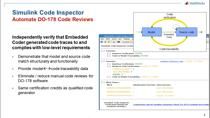
Once you have verified the model, it's now time to also verify the generated code, and this is a highly automated step within MathWorks tools. To run the same test vectors, a unit test that you did on the model level, also on the generated code compiled with your target compiler running on your target system.
So we generate code, either AltoStar compliant, classic, or AltoStar adaptive code, or plain C and C++ code for any environment. The ISO standard recommends using a coding guideline, and a better coder can generate MISRA-compliant code. And this MISRA-compliance can then be checked with a policy-based bug finder to provide the evidence needed to demonstrate that the code is actually MISRA-compliant.
In addition, as I mentioned, you can perform software in the loop or processor in the loop to verify the object code generated from the model. SIL, or software in the loop, means that you compile the generated code with your compiler for the host and run the same test vectors that you did on the model level also on the code, and make sure you get the same results.
Processor in the loop, or PIL, is then using your target compiler and running the code on your hardware. So using MathWorks toolchain, you can set up a framework that allows you to automatically, from Simulink, run the same test vectors on the generated code that you have automatically compiled with your target compiler and download it to your target hardware all from within the Simulink environment.
So with the push of a button, you can also verify that the generated code running on your hardware compiled with your target compiler gives you the same results as your model and thereby have verified the production code that goes into your final system.
We do not only support models, but also, if you have hand code or legacy code that needs to be verified, you can use policy-based code prover and policy-based bug finder, which is our static analysis tools, to verify that that code meets the requirements of the ISO standard.
And of course, at the integration level, where you integrate both the application software for models or hand code together with the basic software, you can also use static analysis tools, like policy-based bug finding code prover, to validate the entire code base that it doesn't have any runtime errors and detect any errors that can occur in the integration stage.
So that was the overview of the reference workflow for ISO 26262, and as I mentioned, this is a reference workflow. And then, it needs to be tailored for your specific application and your specific ASIL level. And that's where MathWorks can support, and I will come back to that later. I would just like to highlight, once again, please ask questions in the Q&A. I will try to answer them during the webinar, during the Q&A session at the end, or we'll try to get back to you after the webinar.
So with that, I would like to hand it over to my colleague, Magnus, who will then take you through the workflow that I just presented but hands-on using a highway lane following case study. So Magnus will show the workflow in practice, showing how you can work with requirements, link those to the models, the code, the tasks, and perform verification activities on your model and code to make sure that they fulfill your requirements.
So here is the Highway Lane following app, and it's a very expensive showcase, actually. It has as a typical highway lane following application. It follows the car in front of you. So if you set your speed on your vehicle higher than the car in front of you, it will decelerate. And if you have a lane that you have to follow, of course, you have to stay in the line, in the lane.
So this is basically what this is doing. It's using LIDAR and sensor fusion in order to keep its position both laterally and also to prevent the collision with the car in front of it. And you can see here that there are a couple of things within this highway lane following application.
This is the device under test, the highway lane following software that we're going to be proving that it's worthy of ISO 26262. And this is a test harness where we actually have some vehicle dynamics, and we have a scenario. We simulate the scenario. And of course, we have metrics to test that we fulfill the in lane and the time gap requirements of the vehicle.
Let's get into the model more in detail and take a look at what's inside. We're not going to be able to follow all the requirements, of course, of this very extensive use case, but we're going to take a look at the lane follow controller within this system architecture model.
If we dig into this one, we can find that there is path planning and data conditioning, but we're interested in the line following controller. And going further down into the lane following controller, we're actually going to find a watchdog braking controller. This is the normal typical in parallel of the MPC controller that is handling most of the situations for the acceleration and deceleration.
But we have a watchdog braking controller, and within this one, we're going to keep track on one requirement through the process that Fred mentioned. We're going to implement and see that the partial braking two requirement is implemented as it should be, and that it's tested as it should be. And all the artifacts are created, and therefore, we have proof of 26262 compliance.
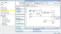
Going further, we want to take a look at, of course, the ISO case study. And what you actually do is just put this in your command window, and if you have the certification kit available, you will get this type of M script in front of you, live script. And you can see that it's a very big table of contents.
It covers, actually, the whole workflow. So if you take a look at what Fredrik presented before, you could actually see that most of the software level description that Fredrik talked about is actually covered here.
Both the software requirements, the software architecture design, the implementation of components, and the static analysis that you do. And also, of course the PIL and SIL is also covered in this use case.
And going further, I'd like to put the context in a higher level and talk about the benefits. Why are we doing this? Why do we base design? We also get early error detection. And of course, since we follow this workflow, we get the automated generated C code and improve software quality through that. And also, we get the qualified software tools automatically using this workflow.
But there are even more benefits that I'm going to talk to you about later. There are a couple of things that I will not be able to touch on during this short time, just 20 minutes, but I just want to mention those before I dig into the application and hands-on looking at the case study.
There are a couple of things in the beginning that are actually quite interesting, and to get a grip of how this 26262 actually works. And especially one thing that is vital, the link between the principal within the standard and the tools that are used in our workflow. And if you're uncertain about how this works, this is the document to look into for that explanation.
Also, in this introduction, in this case study, there is also a picture that resembles the one that Fredrik showed you just a couple of minutes ago. And you can find this also in the documents, and go into the artifacts explorer and to the certain workflow documents for C code. You could actually find this stock-- this image and also the information about what each step is all about.
Furthermore, we have improved. So now, if you don't have any type of software process documents or environment document, we have a template for that for you to use if you need so. Of course, we also have software architecture design. I will not show you that in detail today, but if you want to, you can take a look at it further and of course, reach out to us if you want to have more information about this.
How we can do the dependency analysis, how you can create the different types of stereotypes in order to streamline your design. And of course, you have behavior modeling that we released recently. And we have had for quite a while model views where you could actually see the electrical part of your system, or you can filter out, as in here, the software that has already been reviewed, et cetera. So different types of views for your architectural design.
But enough of that that I will not talk about. Now, I'm actually going to focus on the ones that I will like to highlight today, and they are really vital. Because the workflow that we introduce here is really efficient, and the artifact and test automation makes your daily work as streamlined as it can be.
And how do we prove that? Well, basically, we're going to take a look at how you implement your requirements, how you implement your design, and how you create your tests. And that's how an efficient workflow works and how the Canvas-focused workflow works.
And also, when it comes to artifacts and test automation, there are a couple of artifacts that Fredrik mentioned that you need to have according to the standard, such as the traceability matrix between the requirements and implementation. And also, of course, test. Static analysis, both on model and C code, and of course, the test reports itself for the functional proof that the requirement is fulfilled.
And finally, I'd also like to share the important fact that you can actually, when you've done this on the unit level, all these tests, you can also do an integrational test where you test the whole unit that you would like to deploy as I showed you earlier in the beginning of this presentation.
So let's dig into the present the demo, but actually first, I'd like to show you an even better thing as in Apple presentations. There's one more thing, and that is actually the automation workflow with continuous integration. There are a couple of documents here that like to follow us as well because this is really the nice thing in order to streamline the whole workflow, making it a continuous integration workflow.
So now, let's dig into the presentation of the highway lane following case study. If you run this command, this is what you get. First, a presentation of the whole table of contents for this case study. And you can see here that all the folders for this project corresponds to different chapters in this standard.
So it's very easy to follow along and take a look at different chapters if you are interested in those. We will not be able to follow this in detail today, so I've created a separate to run demo today where we're actually going to go through the requirements, the implementation, and the test as a separate topic. And then after that, show the artifact creation part of this thing, and we finalize with the presentation of the whole thing connected with continuous integration.
So that's the scope of the next step of this presentation. Let's dig into the logic that I presented in the beginning. You remember that I showed you a model or a chart that looked like this. It had a breaking state that we would like to follow and see whether this--
Our requirement or our talk today is actually to see that this step is tested in the correct way, and what we need to do is basically take a look at the requirements that is linked to this implementation. And how to get a hold of that is to click on this link or these three gray areas in this corner here.
If you click here, you open up the requirements perspective, and when you open up the requirements perspective, you get, first of all, all the requirements at the bottom, the details of the requirements to the left-- to the right. Sorry. And also, in the bottom right corner, you get links to the tests, and to the requirements, and to the implementation.
And we can actually see in the Canvas itself that now, we have populated the Canvas with requirements, and we can also see that we have a new icon in the left corner here. And we could actually click on that icon and see what type of requirements are already implemented in this part of the design.
For instance, the partial braking level one is already implemented. You can see that it's already implemented because it's blue here, and it actually has a link to the verification as well. It's blue and yellow. But here, it's white for partial braking level two, and what we need is actually to link to the partial braking two. And what we do is basically a simple drag and drop into the Canvas.
And when that is done, we can then take a look at the requirements. Go to the requirement and take a look at now, it's not white anymore. It's blue, and we're happy about that. One thing more, we have to double check that everything looks good in terms of what it says in the requirement. Then we can see that it's a bit of a typo here actually.
It says partial braking one instead of partial braking two. We need to correct that, and when we do a correction, you're going to see that when that is done, the system realizes that and will inform you that you need to take action and double check that your implementation is correct compared to what the requirement says.
How you would do that is basically go to the link, and click on the link, and just verify. There is a clear issue button here where it can verify and say that OK, the requirement has changed. Does this still fulfill? Or do you have to do some changes on your implementation?
You clear your issue, and you ask the question. Would I like to clear the issue? Yes, I can clear the issue, and you will do the same thing for your link to your requirement.
One thing that I'd like to mention right now is the traceability matrix. That is a way that we could actually check where the requirements are and where the-- Actually, a way also of instead of dragging and dropping your requirements, you could actually use the requirements traceability matrix to do the allocation.
And here's what you have to set up is to the left, what requirement database you would like to look at, and what part of the model on top. And then you generate the traceability matrix.
And when you've done this, you get the whole system, and we're not interested in the whole system because we're looking just at one part. Which means that I'm going to focus the display on just that part.
I'm going to right click and expand, and here, we're going to see that we have now for the watchdog break logic, all the requirements that are written for that part. It does now have a link to a certain implementation.
And if you would like to change it, basically just click on one position and create the link if you want to define it more in detail rather than just the higher level of that block. I also want to mention this Export button. I will talk more about that later, but this is some way you can automate your artifact generation from this one.
So now we have done the part of linking your requirements to your implementation. We now need to take a look at how we can create a test to our agenda. We have covered the requirements part, and we have covered the implementation part. Now, let's take a look at how do we create the test harness for this part of the code?
And I'm going to go up one level and take a look at the test harness for this whole braking logic chart. I'm going to go into the same as I did before. When it comes to requirements, it's always this icon in the corner here. I'm going to choose the test harness for this specific logic.
And there are many different ways you can create test harnesses. Of course, there are many multiple ways of adding input data. It could be from a file. It can be from something that you have recorded.
And this time, it's actually a test sequence block, which is similar to a state chart block that walks through different steps in an effective test case aiming to go through all the different phases of this test case in order to have a good code coverage. And we'll see how good code coverage we'll get using this test case.
So let's run that one. And one thing that you might need to know here is that there is no requirements linked to this test harness. The test harness is just a vehicle in order to do the tests at the later stage in the test manager. So if I run this test harness, there will not be any change in the fulfillment of the requirement.
It will still be yellow because we haven't proven anything by running the test harness itself. What we have to do is go to the requirement and take a look at the link to the test manager. So these are now the test manager links, and let's start with the first one.
Here's the test manager. The test manager, as I mentioned, has a couple of links that are added here in this specific case. All the ones with an asterisk or a star at the end have been modified, so all the others have not been modified. So we're going to take a look at the ones that have been modified.
And of course, the requirements, you will recognize them. We have been looking at them before. Partial braking two, we actually linked ourselves just a couple of minutes ago, and the system under test, you could actually segue to this braking logic if you're uncertain which one it is.
So clicking here would actually jump us right away to that exact device under test. And the same for test harness. If you click on this link, you will segue to that test harness double checking that it's actually the correct one that you want to use.
Continuing through the test system or the test manager, there is also baseline criteria. We have now a file that we want to compare with. We have figure out the correct answer to this. Maybe we have a executable requirement specification that we can generate the correct data from.
Or in on the other way, we have to figure out the results that we need to have a correct behavior. And of course, at the end, we have coverage data gathered when we were running this test.
So what I'm going to do right now is actually to mark this test and mark run, and we're going to execute this and take a look at the data, how it behaves. And while we're running, we're actually going to see the execution on the left side of the model as well.
So we actually got a pause. We can see that if we look at the baseline criteria and click on one signal, we can see that we have passed the behavior. No brake, P1 brake, and P2 brake, F brake are occurring exactly when they should, as anticipated.
And we can think, OK, great. Now we have a mark here. The test case is done. But actually, if you take a look at the requirement-- And I'm going to walk through the requirement now. We're actually going to see that we don't have fulfillment yet. It's still yellow.
And the reason being we haven't done the seal test, and the seal test, as you might remember from Fredrik's presentation, is the comparison between the code that is generated when we're running the model and the C code. So the difference with this test is actually that we have two simulations, and we compare them with each other.
Since we only have 20 minutes in this presentation, I have prepared for a video showing this. And before I do that, I also want to show you the coverage settings as of now. If you look at the test case that we actually just ran, if you click on that test case further down, you can see the full coverage. And you can see that decision is 70%.
We haven't been able to create a test that is actually giving us 100% good coverage. And one way of looking at this is actually clicking on the model, and you will get the code coverage, the current code coverage, for this model.
And we just give it a couple of seconds, and it will calculate. And you can see which of the transitions that are actually fulfilled. You can see that we actually did not do that well, and we need to improve that. And that's what I'm going to show you in the next video in order to speed up.
So here is the situation. We started out with a test case that we only had the TC1. Now we want to run the SIL as well. I can speed up a bit, so we see. Now we run this TC1, and after that, we're going to run SIL as well.
And when we have run both of them, we will see that we have a clear mark on the requirement partial braking two. So now, we're running both the model code and the generated C code, and we can see that now, we're happy because we have a verified requirement.
Both the SIL test and the TC1 is approved. Going further, I mentioned that the code coverage was not perfect from the beginning, so we needed actually to add a couple of more tests. We have done that now with the design verifier, and I can--
If you're interested in that tool, we can tell you more about it. But basically, what it does, it's looking for the missing test of your design. And you can see here by using that, we can now prove that all the decisions, all the code is executed.
And that brings us back to the next part of the presentation. We have talked about all the testing. We have talked about the linking of the requirements. We have talked about everything but actually showing the results that you can create when you have run the test.
So basically, what you can do is to create the report when you have done a-- executed a test. And for instance, we have a couple of ones already prepared that I can share with you.
For instance, here is a document that describes the exact test that we showed-- That I just showed you, which is basically going through the different partial braking steps of the model.
And of course, we can do better. We can even use continuous integration for all these tests and all these artifacts. And I'm going to show you one more thing, and then we'll wrap this up and ask Fredrik to finalize the whole thing. Let's see.
So when it comes to continuous integration, we could actually interconnect with your process that you already have for continuous integration. And by using, for instance, Jenkins, you can get all the artifacts. You can start the traceability matrix. You can run all the tests while you're pushing in your new code into your development process.
And that's a cue for you, Fredrik, to continue discussing the things that are outside this process.
So now we have come to the last part of the presentation, which is how MathWorks can support this. So as I mentioned in the beginning, we support this both through our tools that you have seen now, how the different tools in MathWorks's portfolio can bring together this one integrated workflow for ISO 26262 with all the verification activities that are needed to fulfill the ISO standard.
But not only that, we also have expertise within MathWorks, consultants that have long experience on working on customer projects with ISO 26262 and MathWorks tools to make sure that we can help you to quickly get a workflow up and running, which is adopted to your specific needs and your specific application.
So to elaborate a bit more on that, this workflow is not just about the tooling and the activities, but it involves a lot of things around it, which is also important. And for instance, we may have external requirements.
So we got some questions in the chat or in the Q&A regarding integration with external tools. So I can come back to that during the Q&A, but basically, you can import requirements from different tools. And depending on which requirements tools that you're using, that integration may look different.
And that's where MathWorks can help to provide the best solution for integrating your requirements into MathWorks tools, so you can start to link and trace those requirements to your models, and code, and so forth.
The overall life cycle management is also something where it needs to be addressed, and where we have a lot of experience on working with that. Risk process analysis, generating customized reports for your specific needs or templates, and as Magnus mentioned, regarding continuous integration. How can you make sure to automate some or all of these tasks in a continuous integration way with Jenkins and so forth?
So for these things and also related to the actual ISO 26262 workflow, we have developed this ISO 26262 process deployment advisory service. So it's a ready-made framework where we can go in with our expertise from customer projects ISO 26262 in our workflows and tools, and familiarize ourselves with your current environment.
What tools are you using for requirements management? What is the hardware target? The embedded hardware that you're targeting? What is the ASIL level? What does your current workflow look like? So basically, get an understanding for what your goals are, and where you are now.
And from that, we can provide a gap analysis to basically analyze and give recommendations on these are the goals for or recommendations from ISO. This is where you are right now, and these are the gaps that you need to fill. And maybe the priorities and what should actually be done.
And from that, we can actually help you with detailed instructions and also actually do the work, or some of the work, ourselves. So you can outsource some of that work to MathWorks to provide you with parts of this to make this integrated workflow streamlined. And here is an example from Autoliv. We used our MathWorks consultants for an ISO 26262 project successfully.
Thinking or talking about successful projects. So here is an example from KOSTAL, who developed an ISO 26262 ASIL D certification reached, ASIL D certification, which is the highest safety integrity level for their electronic steering column lock software.
And not only were they able to get the ASIL D certification, but as you can see here from the results, they actually managed to cut the development and certification time by 30%. And the reason for that being, of course, that using model-based design, they could test and verify earlier using models. And also using the work that we at MathWorks have done to provide the workflows, the templates and everything, the actual time it took to produce the necessary artifacts to show the results was actually also reduced.
Here is another example from LG Chem developing a battery management system for the Volvo XC90 plug-in hybrid. They received ASIL C certification, and by using model-based design with our safety workflow, they were able to reduce the software issues by more than 50%.
So where is all this information gathered that we have presented today? We have a product called the IEC Certification Kit that contains the use case that Magnus presented. It contains all the documentation about the workflows that we have presented, the mapping between the workflow and the ISO standard, all the conformance demonstration templates for you to--
Which are ready for you to show the evidence according to this workflow, and all the other work that we have done with TUV SUD like the certificates and so forth. So within this product, as I mentioned, there is the case study.
We have this artifacts explorer where you can explore all the artifacts that we have. So it's basically documents like the assessments from TUV regarding approving the workflow and the tools suitable for ISO 26262 development.
When we talk about ISO 26262, when you use tools, whatever tools you use, they should be defined tool use cases. If we don't provide those, you need to do that for all the different tools, so we have provided all those tool use cases, tool classification, workflow conformance according to the standard. So you don't need to do that. We have done all of that work up front.
So all of that is gathered within the IEC certification. And we will share after this webinar links not only to the presentation, as we received a lot of questions about. So you will receive the presentation afterwards. The presentation will be recorded, and it will be available on our website in some time. I'm not sure exactly how long that will take.
And also, we will provide you links to the IEC Certification Kit and all other relevant products that we have used today, so you know what tools that you need to actually execute this workflow or this case study. I would like to thank you all for attending this webinar.
Featured Product
IEC Certification Kit
Up Next:

Related Videos:


Seleccione un país/idioma
Seleccione un país/idioma para obtener contenido traducido, si está disponible, y ver eventos y ofertas de productos y servicios locales. Según su ubicación geográfica, recomendamos que seleccione: United States.
También puede seleccionar uno de estos países/idiomas:
América
- América Latina (Español)
- Canada (English)
- United States (English)
Europa
- Belgium (English)
- Denmark (English)
- Deutschland (Deutsch)
- España (Español)
- Finland (English)
- France (Français)
- Ireland (English)
- Italia (Italiano)
- Luxembourg (English)
- Netherlands (English)
- Norway (English)
- Österreich (Deutsch)
- Portugal (English)
- Sweden (English)
- Switzerland
- United Kingdom (English)