Modeling a Hydrogen Fueling Station
Learn how you can use Simulink® and Simscape™ to model a gas system through a case study on a hydrogen fueling station model.
Watch how to:
- Model different components of a hydrogen fueling station, such as a hydrogen fuel tank, a compressor, a chiller, and a dispenser for fueling the vehicle.
- Incorporate sensor readings in the model to perform calculations on gas pressure, flow rate, and mass.
- Add multidomain physical effects such as gas cooling, pressure changes, and heat flow.
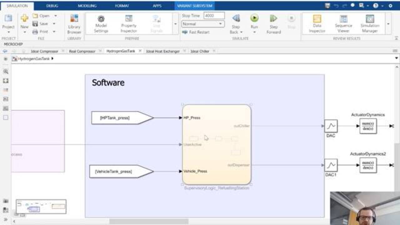
- Design supervisory logic and feedback control algorithms for software that manages key aspects of fueling station operations, such as controlling mass flow in the compressor.
- Parameterize components and switch between component variants such as an ideal compressor and a real compressor.
- Run simulations with different system configurations and measure key metrics in system operations to ensure the safety, efficiency, and durability of the fueling system.
Vasco Lenzi is senior application engineer at MathWorks Switzerland. He specializes in design automation with emphasis on multidomain modeling, control design, verification, and deployment. Prior to joining MathWorks in 2016, Vasco worked as a development engineer on the modeling and simulation of engines and hydraulic systems at Liebherr Machines Bulle. Vasco also worked as a control software developer at the Institute of Dynamic Systems and Control, ETH, with active participation in Formula Student competitions. He holds a BS in mechanical engineering and an MS in Energy Sciences from ETH Zurich.
Published: 16 Sep 2022
Interaction in modeling gas system with Simscape. This is something that happens in a library called Simscape. We have low-pressure supply of hydrogen, which has been then, thanks to the compressor, go up to 950 bar. And in this test cases, we are going to run in the model. We are going to do this in one hour.
Then there is a chiller. Then when the time is right and the dispenser is activated, it's always keeping a very low temperature of the gas flowing into the vehicle. This is necessary to avoid a big temperature jump in the vehicle tank.
The idea is that after one hour when we reach the right pressure, the vehicle, which is empty, is only 30 bar in the tank. It's going to be refueled to 700 bar. We're going to put 6 kilos-- this is the requirement we have of hydrogen in our vehicle tank. And this should last less than five minutes.
Did one shortcut to the model I want to discuss today. And this is the model we're going to look together. It's a nitrogen gas refueling station. We have the low-pressure supply like in my architecture.
We have a compressor inside a subsystem. You see this pink line. We're going to discuss about it later on, but this is the flow of hydrogen, which is physically connected between the different components. The heat exchanger before going the high pressure buffer storage we have the chiller. We have the high pressure valve.
We have a small pipe that goes to the dispenser, which is kind of the things attached to the vehicle delivering the hydrogen gas. And then we have the vehicle tank. And then we do some calculation such as integrating from the initial mass. We integrate the vehicle tank so that we can have the total kilos.
And just to take a look at example on the compressor. Let's go in it. We can see that we have two possibilities. These are called variants subsystem. I have an idea compressor and a real compressor.
And if I look in my ideal compressor, this is simply mass flow. Simply a mass flow. I can give any mass flow, and it's going to keep this mass flow from point A to point B. And so there is real hydrogen flowing in.
The same can be seen in the heat exchanger where we actually have a model the pipe which is exchanging heat with the rest of the environment. And this is the real cool things about Simscape. You get so to speak more color and each color is associated with a new physical domain. And so you have the heat flow taking heat out of the pipe and putting it into the ambient temperature.
In this case, we are using an ideal heat exchanger. We're just giving power to take away heat from the pipe. And we can then size and dimension the necessary heat exchange that we need to make this storage work, this refueling station work.
So I ran the simulation now for 40,000 seconds. You can see down below that now what happens is that I defined-- each component brings its own equation to the entire system. There is a compilation part in which the entire state space basically is calculated based on all the components attached to the physical network. And this is then inside inserted in our powerful solver and simulation engine, and then it's simulated.
And then we are going to see that this model is actually exceptionally fast. Of course, it's not very complex. And to repeat what we achieve. We want to do is we want to bring the first hour to fill up the compressor and then start the vehicle tanking process.
So we can see here that it starts the simulation down below. It goes from 0. It's already after one hour and then there is a bit of more slowness when we are charging the tank. There is a lot of physical things happening there during the tanking process. The simulation slows down a bit and then it stops. And we get the result back.
Such a simulation like I did right now can be quickly put together using ideal components such as ideal compressor. This is not physics at all. It's just we control the mass flow going into the system. We control the heat taken out of the system.
And so it can be used to start sizing up our system, seeing if everything is all right without really going into the details of our physical domain. It can already be coupled with part of the software to see if our logic and whatever we achieve that we want to do, such as opening up the valve of the flows into the chiller. Then after two seconds, opening it up the dispenser to start the tank charging, refueling process. And then once the vehicle pressure is more than 700 bar, we can close it off.
So you can really start combining software logic and a very high level physical model. But nevertheless with time, you can increase the complexity of your model. I will do that when I switch to the real compressor so that we can compare the two simulation run. If I open up the data inspector, we can look at key performance.
We wanted to see if the vehicle tank flow. We see that after 3,700 we go up to around 20 grams per second, which compares to more or less 1.5 kilograms per minute, which is what expected on today's hydrogen fueling station. I can measure if I meet my requirement of 300 seconds. I see that I-- thanks to this cursor-- I am at 303.
So I'm almost there. Fulfill the requirement we can say. And we can fill up tank. But how much did we fill up? We can plot a total mass that's flowing . And we see we start from 300 grams of hydrogen. And in the end, we have six kilograms.
So actually, we reach six kilo around after 250 seconds. So this is fully complying with our high level requirement. We can really use this simulation to get all this KPI right. How much should flow from the dispenser to the vehicle tank.
We can as well clear this plot and plot something like the high-pressure pressure. So the compressor work. We see that we start from 30 bar and we bring it up to 950. After more or less 3,500 seconds, we are there.
And down below, we can see maybe the temperature, the high pressure storage temperature. The gas, of course, heat up while it's being compressed, but we have a heat exchanger that can keep the temperature in check around 60 degrees. And then we can take a quick look at the total power needed, for instance, to keep the gas after the chiller at minus 40 degrees.
This is very often done in this kind of refueling station. We have a chiller after the high pressure storage. We need to keep the gas at around minus 35, minus 40 degrees so that we don't have a big spike in temperature when we are bringing it into the tank. And we can see that here as well in the tank temperature.
There is a big spike. It comes to around 60 degrees, but this is not dangerous. This is full acceptable. So I did my tanking process in a safe way.
Let me just quickly do one less simulation to showcase the difference with a real compressor. We can go inside a compressor to take a look at this new block. It's a positive displacement compressor and can easily be parameterized using your data sheet of your machine, parameterizing their machines. And so you can re-found the same things here.
You can put kilogram per hour as a mass flow, what would be the nominal shaft speed and what would be the nominal pressure ratio and the volumetric efficiency. And these things can always be checked. There is very often a fluid where you can plot key characteristics of component. In this case, is the volumetric efficiency versus the pressure of the compressor.
So let's simulate with this block. Quickly compare it. As we can see here already, this is one of the many blocks that combines two domains together. We have the pink one for the gas. And then we have the green one for the mechanical part.
And so there are a lot of these multi-domain blocks within Simscape that allows you to build up truly this multi-domain simulation. I cancel all the subplots. Let's put just one.
And the nice things about the dot inspector is I can always see my past simulation. So I have the mass flow of the compressor. In this case, the ideal one we can see is just like I give a constant. And then we can take the real compressor mass flow. Let's put it in green.
And we can see how this respect truly reacts to the different pressure differential that you have from port A and port B. This works around the nominal mass flow. And so we already have more precision in our system. But we see we can use the mass flow to size it up. And then we can put the real component to see how it all fits together in a more dynamic way.
We try to put together for you the relevant Simscape domain for hydrogen system modeling. They go from thermal exchange, like we saw the temperature, to mechanical, like we saw with the compressor; electrical, this for the fuel cell is going to be very important; thermal liquid for the electrolyzer with the water coming into the system; gas, two-phase fluid, and moist air. These all come off the shelf as a shipping library.
Related Products
Learn More

Featured Product
MATLAB
Up Next:

Related Videos:


Seleccione un país/idioma
Seleccione un país/idioma para obtener contenido traducido, si está disponible, y ver eventos y ofertas de productos y servicios locales. Según su ubicación geográfica, recomendamos que seleccione: United States.
También puede seleccionar uno de estos países/idiomas:
América
- América Latina (Español)
- Canada (English)
- United States (English)
Europa
- Belgium (English)
- Denmark (English)
- Deutschland (Deutsch)
- España (Español)
- Finland (English)
- France (Français)
- Ireland (English)
- Italia (Italiano)
- Luxembourg (English)
- Netherlands (English)
- Norway (English)
- Österreich (Deutsch)
- Portugal (English)
- Sweden (English)
- Switzerland
- United Kingdom (English)