Optimized Motor Control Applications: From Idea to Deployment with NXP MBDT
Razvan Chivu, NXP
Stefan Cinipeanu, NXP
Developing complex applications for motor control requires a streamlined, efficient process that delivers high-performance results. In this presentation, explore NXP™ Model-Based Design Toolbox (MBDT), which seamlessly integrates with MATLAB® and Simulink® to provide an automated path to applications development on NXP S32 microcontrollers. With extensive automotive math and motor control function libraries, peripheral driver blocks, and processor-optimized motor control functions (running on a specialized co-processor, the Enhanced Time Processor Unit), the toolbox offers multiple simulation modes and code generation capabilities for NXP processors. By using MBDT with MATLAB and Simulink, NXP customers can easily prototype motor control applications. Discover how NXP MBDT enables the development of optimized performance applications for motor control.
Published: 7 May 2023
[AUDIO ID]
Hello, everyone, and welcome to our session. My name is Razvan Chivu and I'm the Manager of the Model-based Design Team from NXP. And I'm also joined by Stefan Cinipeanu, a Senior Software Developer from the same team. Today, we would like to show you how Model-based Design can speed up your development, and how it could translate ideas into embedded designs directly from Simulink using NXP's toolbox. Now let's see exactly what this means.
Firstly, we will briefly introduce you to NXP and the ecosystem of solution it provides. Then, we'll get to know the Model-based Design Toolbox and maybe see how it integrates into such an environment. And next, I'll pass it to my colleague Stefan, who will talk about motor control solutions with the S32K39x and how you could use Simulink to develop and even optimize them by running parts of the algorithm on a dedicated motor control co-processor.
But before we get into all these details, if you'd like to see a real example of how these tools could help speed up the development process, you can read this recent article about an US company that managed to get from a virtual vehicle to an all-electric off-road UTV in less than a year with only three engineers using Simulink software and NXP hardware plus, of course, the Model-based Design Toolbox. You can read more details about this great achievement using this QR code.
Now getting back to the presentation at hand, as a small teaser, we'll get to see this happy motor spinning, and importantly, how all these tools can do some heavy lifting to make the development easier. But first of all, let's talk a little bit about the context.
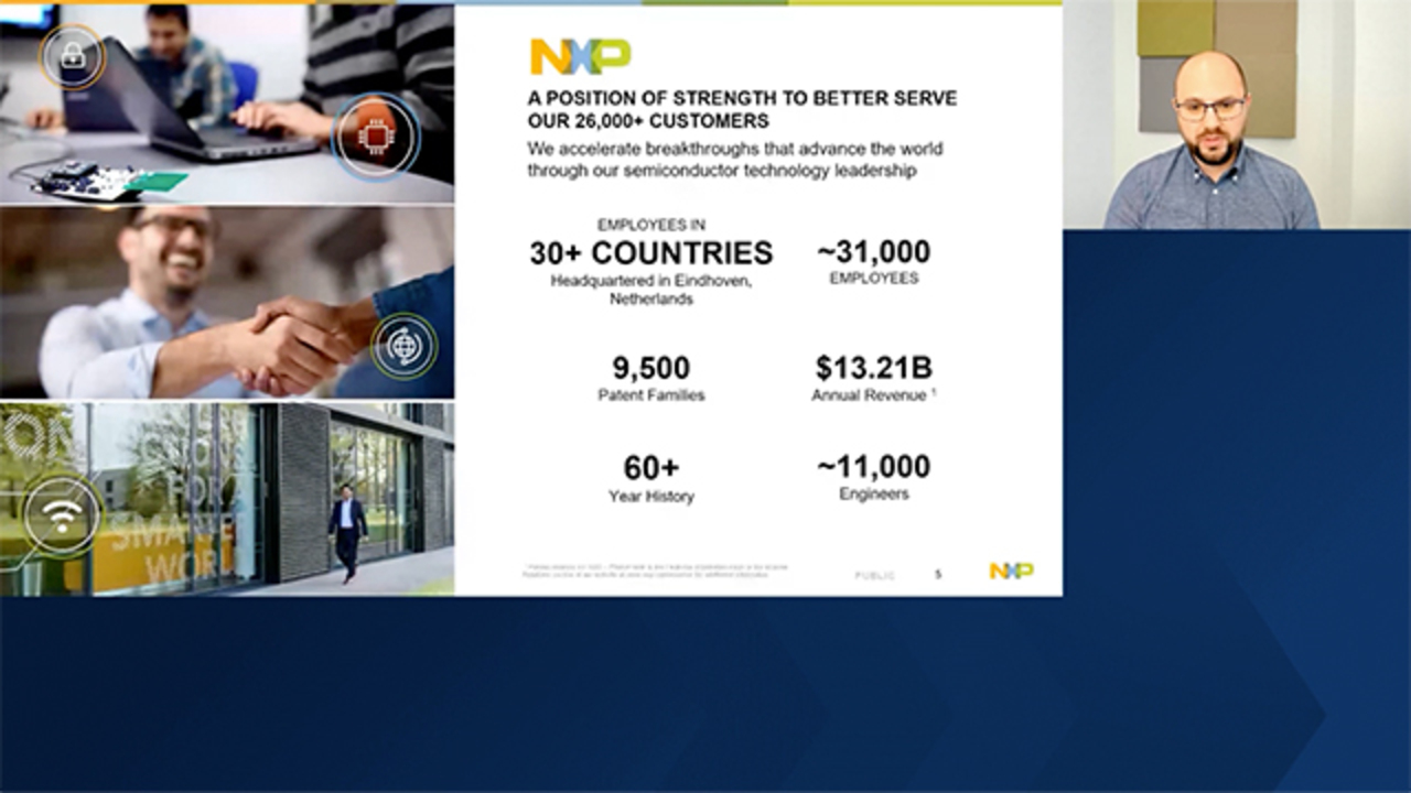
So NXP is a company with more than 60 years into the semiconductor manufacturing and design business, which provides solutions for anticipating and even automating people's needs, from the first taxes to services directly from our smartphones all the way to smart city solutions, to robots, and even machines in industrial domains. NXP addresses challenges where aspects such as performance and reliability are critical.
Its focus on safety, security, and connectivity has established NXP as a key player in the semiconductor industry consistently driving advancement in technology. And to keep all these solutions connected and integrated in our world, a large processing power is required, and that is offered by NXP through the application and devices it delivers. Now let's take a look at the ecosystem behind it all. So in the center, we have the processor providing the computational power plus a rich selection of peripherals.
And of course, for all the hardware, NXP delivers extensive documentation as well. And on top of that, we get to the first layers of software provided. Some examples from this layer would be the real time drivers that are able to control the MCU and the automotive math and motor control library, AMMCLib for short, which is optimized for best performance. Going to the next layer, we get to the tools. Here, NXP provides everything in terms of IDs, debugger, tool chains configuration tools, so on, and so forth.
And the last layer here would be the reference designs. Here, NXP shows the capabilities of real applications implemented on top of our hardware and software solutions. Now, let's take a look at how all of these interact with engineers on a daily basis. So this would be a representation of a workbench, if you may. While we have on the left side the hardware NXP is providing, on the right side, we can see what is usually needed for the development of embedded applications.
So something like an ID to develop, configure, build, debug the code, and a graphical way of visualizing the data from the embedded target. Let's take a closer look. So this is the Institute of Design Studio, an integrated development environment, which lets you write the application code and may be using the drivers and libraries NXP offers, build that code, flesh it onto the target, and debug it. Moreover, it has other tools integrated within like this two to configuration tools. And what are those?
Well, these are graphical user interfaces that reduce the complexity of configurating the UI. It you know when that. After you have everything configured, it simply generates all the code for you.
So something that is verified and validated to work that you can use in all of your applications. And you can have this configuration tool implemented for pins, what you are currently seeing, but it's also available for something like clocking tree and peripherals as well. OK, so not that we saw the idea, let's take a closer look at what a FreeMaster monster as we call it really is. So this is a data visualization tool where you can monitor data on the embedded targets using these oscilloscope like displays or even seeing the numerical values directly.
And using this tool, you can also develop more complex UIs, where you can control how the data is shown and how you can interact with it. And of course, you can also export that data to be used in some other process, maybe outside of the tool, if you need it. So to recap, we saw how all of this work together. So we have the hardware we have the software, drivers, and libraries. We have the tools for configuration, build debug, and even this data visualization tools.
So this pyramid is what we call the NXP ecosystem. But I would now like to digress and talk a little about the Simulink ecosystem, because we know that MathWorks has a lot of complex state of the art software products that are developed by subject matter experts. And we thought that it would be great if we could somehow leverage all of these products as they can generate hardware agnostic code. The only problem here was, this code would not run as is on our embedded targets.
And this is exactly where our Model-based Design Toolbox comes into play. We have created basically a bridge between the two worlds, or a gateway as we usually call it. It makes the two ecosystems really work together, so that you could develop Simulink models using various toolboxes provided by MathWorks, leveraging this power to run on the NXP hardware, and even use something like the peripherals or pins to sense and act.
So as we will see to today in this presentation, how you can get motor to spin directly from Simulink. And having access to this whole new or bigger ecosystem enables you to test and integrate at every step of the development phase, and it also means that you should achieve a faster time to market, and also have this easy to use and reuse models, plus, of course, the hardware independent simulations for your algorithms. So let's talk a little bit from the user perspective, because this is a very simple process.
You develop the Simulink model, then just click one button, this build button that you can see in the image. And after that, the code gets generated, built for the embedded target, and uploaded automatically onto it. All these different parts of the code generation are handled behind the scenes by the tools, so you don't have to pay attention that there is a hardware agnostic part generated from Simulink products, a configuration part generated from our tools, and even this kind of hardware aware part generated by our Model-based Design blocks.
It all simply happens at the click of a button. And as for what we are covering with our Model-based Design Toolboxes, you can see in this diagram what hardware support we are currently providing, but maybe I would like to mention that although we are focusing on the automotive area, we are also developing toolboxes for industrial, internet of things, vision, even radar.
And maybe also important to note here is that you can find interesting examples that we have on subjects like motor control, battery management systems, even hybrid electrical vehicles, radar vision, AI and ML. All of these using our toolboxes. Now that they give a quick overview of the context and maybe the value proposition, I will pass it to my colleague Stefan to walk you through a real use case to see how a motor control application could be developed on something like NXP's S32K396.
Thank you, Razvan. Hello, everyone, and welcome to our session. After Razvan has introduced you to Model-based Design workflow and what NXP offers as a tool in this direction, it is time to present what NXP also provides in terms of motor control solution, and how this kind of complex application can be achieved using the Model-based Design Toolbox. In this direction, NXP has introduced the new member of the S32K3 family, the 32K39 MCU for electrification applications.
This multicore MCU based on ARM Cortex M7 processors running at the speed of 320 megahertz comes as an extension of the K3 family for its high quality capabilities in the areas of motor control and battery management system applications. We've highlighted with red the most important features for what we are interested in today's presentation. This new MCU has a particular feature that empowers the motor control application, and that is the enhanced time processor unit.
Shortly, the eTPU is an accelerator, a core processor that has motor control capabilities such as software resolver for angle and speed estimation of the rotor, analog sensing for phase currents and voltages, implementation of field oriented control algorithm, and pulse width modulation capabilities. This unit can offload the entire main core from the motor control task. In the context of electrification, this feature is highly appreciated, because while eTPU performs the motor control task, the main core can execute, for example, a VMS algorithm.
Having this in mind, we propose a first motor control configuration, where the eTPU performs the software resolver task, and the FOC algorithm runs on one of the K39 cores. The ultimate goal will be to completely offload the core from the motor control application, letting the eTPU to perform entirely this task. But in today's presentation, we are going to dive into the first configuration. So we have the main FOC algorithm running on the CPU, and we can explore our hardware setup.
We have our model with the resolver sensor attached to its shaft the PMSM motor is powered by a 3-phase inverter, which is controlled by a pre-driver. The phase currents and voltages are measured by the ADC along with the body control triggering unit for multiple high resolution measurements. A specialized digital signal processor handles the result of all signal measurements that are fed to the eTPU. A signal generator is used for the resolver station.
And for better performance, the DMA peripheral will transfer the measurements data. After the FOC algorithm computes the optimal commands, the enhanced flex pulse width modulator performs PVM commands updates for actuating the motor phases. Logic control unit handles the synchronization between analog measurements and PVM updates. To summarize the harder set up, we have two main subsystems, one that executes the actuating part of the motor phases, and the other one for analog sensing and software resolver.
In terms of software architecture, the main emphasis algorithm is developed under a finite state machine that also handles the alignment of the rotor calibration and fault detection. The entire application is interrupt-driven. In this way, after the phase current's measurements are done, an interrupt is triggered, and the routine that handles it will give the measurements, perform an initial fall detection, and execute the state machine that we've just presented earlier.
Now that we have our hardware and software architecture, let's see how can we achieve such a complex application using the Model-based Design Toolbox. The classical way of work was starting to code using an ID, for example, the S32 Design Studio. NXP also delivers the RTD for peripherals initialization and control. Using a configuration tool, you can easily configure and initialize the MCU in terms of clock spins and peripherals.
For such complex application as motor control, you would probably want to use some pre-compiled libraries like automotive math and motor control library that NXP also provides. Together with the application source, you are going to compile the project to obtain an executable file that will be flashed on the target. Then with free master tool, you could visualize the data and perform real time debugging.
In the Model-based Design approach, things are simpler because using the MathWorks ecosystem you can develop much easier Simulink models and with the click of a button, all the build, deploy, and start phases are encapsulated by the Model-base Design Toolbox that uses all the drivers configuration structures and pre-compiled libraries. The final result would be a generated application running automatically on the target.
We have prepared a demo to demonstrate how such complex application can be rapidly prototyped using the Model-Based Design Toolbox, but first, let's check out the hardware setup. We have the PMSM motor with the resolver sensor connected to a 3-phase inverter that is controlled by the K39 MCU. FreeMaster is used to visualize the current, voltages, and speeds. We've developed in Simulink the model that was built and deployed on the hardware.
Let's take a look to our Simulink model developed for the setup that we've just presented. Clicking on the build, deploy, and start button, we can see how the model is analyzed. And based on it, the code is generated, cross compiled, and downloaded on the target. Now, if we go on the embedded coder app, we see the view code button. You can click it, and explore the sources and the generated code of the Motor-control Model. Let's open the FreeMaster project attached to the model.
We are going to add the camera with our hardware setup. After we make some connectivity configurations in terms of moderate and communication port, we connect to the target and start the application from the On/Off button. You can observe the calibration and alignment phases, and we set the desired speed of 100 RPM to see how the motor behaves. Also, we change the desired speed and we also applied some load on the rotor to observe the behavior of the FOC algorithm in the presence of external [INAUDIBLE].
Also, we can reverse the direction of the motor spinning by introducing a negative value in the desired field that represents the RPM. In the FreeMaster project tree, you can explore other scopes for diverse parameters like PVM command updates, the dq-axis currents and voltages, and so on.
Now, if you are interested to speed up your work using the NXP ecosystem and MATLAB in a similar way we've just presented, you can install our toolboxes directly from MATLAB add-ons or you can download them from the NXP website. All the toolboxes are free of charge. If you have questions, feedback for us or encounter any issues, you can open a thread on our community space. Here you can discuss directly with the engineers behind these toolboxes.
You can also follow our trainings and courses like the beginner's guide series or even more particular application demos focusing on motor control, VMS, and AUTOSAR. Thank you very much for your time and attention. Now you can address questions in the Q&A section where we are ready to answer and provide additional details if needed.
[AUDIO ID]
Related Products
Learn More
Featured Product
Simulink
Up Next:

Related Videos:


Seleccione un país/idioma
Seleccione un país/idioma para obtener contenido traducido, si está disponible, y ver eventos y ofertas de productos y servicios locales. Según su ubicación geográfica, recomendamos que seleccione: United States.
También puede seleccionar uno de estos países/idiomas:
América
- América Latina (Español)
- Canada (English)
- United States (English)
Europa
- Belgium (English)
- Denmark (English)
- Deutschland (Deutsch)
- España (Español)
- Finland (English)
- France (Français)
- Ireland (English)
- Italia (Italiano)
- Luxembourg (English)
- Netherlands (English)
- Norway (English)
- Österreich (Deutsch)
- Portugal (English)
- Sweden (English)
- Switzerland
- United Kingdom (English)