System Modelling & Simulation of an Electric Two-Wheeler: A Journey from Virtual Prototyping to Production
Overview
Designing a 2-W EV for optimum range and performance requires careful consideration of powertrain component sizing such as batteries and motors, their placement on the vehicle for improved ride & handling, and robust design & testing for operational safety. Whether you are retrofitting an IC engine vehicle with electric powertrain or designing a new one, virtual vehicle simulations can help you gain insights into real-world behavior, perform testing for different what-if scenarios, and verify the functionality of embedded software. Frontloading development in this way helps speed up variant assessment, study edge case scenarios safely, and improve the overall product quality.
In this webinar, we will demonstrate how MathWorks products can help you perform these design activities for an Electric Two-Wheeler. Specifically, we will cover the following points:
- Performance Analysis – component sizing, component selection, 0-60 kph time, and range optimization
- Controller Development and Testing – ABS algorithm development, regenerative braking algorithm testing, Vehicle Control Unit and Battery Management System.
About the Presenters
Abhisek Roy, Senior Application Engineer, MathWorks
Abhisek Roy is a Senior Application Engineer at MathWorks India focusing on Plant Modeling, Control Design and Automation. He has been working with Automotive customers to address their challenges in the areas of powertrain modeling and vehicle dynamics studies. His areas of interest include the study of various automotive systems and controls systems. Abhisek has completed his M.Tech in electrical engineering from the Indian Institute of Technology, Madras, specializing in control systems and robotics, and B.Tech in electrical engineering from Jadavpur University, Kolkata.
Prasanna Deshpande, Manager – Application Engineering, MathWorks
Prasanna Deshpande is a Manager of Automotive Industry Application Engineering Team with MathWorks India and specializes in the field of Automotive Electrification, Model-Based Control Design, and Automation. He and his team members closely work with Automotive OEMs, Suppliers, Start-ups, and Services in adopting Model-Based Design for system simulation, embedded code generation and real-time testing. Prasanna brings more than 16 years of experience with various clients from the automotive industry. Prior to joining MathWorks, Prasanna was working as technical leader in the automotive group of KPIT Technologies Ltd., where he gained expertise in rapid control prototyping and hardware-in-the-loop simulation technologies for various automotive customers. He has also worked as an assistant manager at Mahindra & Mahindra Ltd. Prasanna holds a bachelor’s degree in electronics and a master’s degree in instrumentation from University of Pune.
Recorded: 20 Sep 2022
This session is part of a three session series that we will be hosting this week under the theme of Two-Wheeler Electrification, where we will take you on a journey of building your vehicle from prototyping to production. In today's session, our focus is going to be on system level simulation of the entire vehicle. You will see that we will talk about vehicle dynamics, rider handling analysis, as well as focusing on different components like batteries, motors, bringing them together to formulate the system level simulation.
In our next two sessions, the one tomorrow and the day after, we will take a deeper dive in battery modeling as well as motor control design. In the battery session, we are going to take you through modeling the battery pack from cell to module to pack, performing its thermal analysis, doing state of charge estimation, and developing a full fledged battery management system. So we hope you will join us for the next two sessions as well.
For today's session, let's start with our speakers. And I would like to welcome Abhisek and Prasanna, both of whom are my colleagues at MathWorks. Abhisek is a senior application engineer and also a resident expert focusing on automotive applications. He is an alumni of IIT Madras and works with many of our customers in developing their electric powertrains, vehicle dynamics, and other applications in the automotive domain.
Prasanna Deshpande is manager of the automotive application engineering team based out of Pune. And he is our domain expert who works with OEMs, suppliers, startup. And today, he will be with us sharing insights on their technical business challenges and a lot of interesting things.
[AUDIO OUT]
And over the years, I've had the opportunity to work with several of our customers globally. And today, along with Abhisek and Prasanna, we will take you through the next hour with a lot of interesting applications in context of two-wheelers. So to get us started, I would like to invite Prasanna to tell us more about the trends and challenges that he's been seeing and sort of a pathway or overall design workflow that he sees in terms of going from prototyping to production. Over to you, Prasanna.
Thank you, Shripad. So Shripad, thank you for the introduction. I have been working with multiple customers in the automotive market-- in the Indian automotive industry. Some of the customers are Indian domestic customers. Some of the customers do have good partnerships globally also.
So to start with, let's start with some of our observations that we have built by working with electric two-wheeler industry, how they are building their prototypes, and how they are going from prototyping to production. Maybe to start with, the initial prototypes of many of these vehicles are built using system integration approach. What I mean by that is several companies build initial prototypes by sourcing different components from suppliers.
They integrate the systems. And they test these systems. A few companies also go ahead and start selling these components. Maybe the motivation towards selling the vehicles by assembling components is to test the market, to test some success so that they can attract more investments and do things.
Then the next step is typically going for in-house design and development. This is typically done one thing at a time. In India, it makes a lot of sense for a lot of companies to do battery or battery management in-house. Design and manufacture in India, I'm sure all of you know, the government of India does give subsidy as per the frame to norms for companies who design batteries and BMS in India. And slowly, it would also come towards motors.
So the reasons for doing battery and BMS in-house, one thing it helps you to attract government subsidy. Another thing is you build your own IP. And you can attract investors if you're a startup company. Also thirdly, and the most important thing is it's a beginning of building your own identity, your differentiator in the market.
It's the hardware on top of which your software, your differentiating features are going to reside onto. And that's where the third thing comes into, the differentiating features. In the electric two-wheelers, it is very clear now that the differentiating features are a lot of software-driven features. So what I mean by that is a lot of differentiating features are defined in terms of cruise control, then hill-hold, then ride saddle sticks, live location, proximity log, phone connectivity, several app-based services, and things like that.
So if we quickly go back to the in-house design and development phase, that phase is basically where a company starts doing things in-house. So that's where they need to start thinking about their requirements, their architecture, what kind of things they are going to do. And this is where several technical challenges are faced. It's like component selection, choosing the right battery chemistry should we use for an MC or LFP lithium ion batteries for the given need of that vehicle.
Then should we use an induction machine or a PMSM or nowadays there is a big trend in terms of switch reluctance motors also, the SRMs also, so which type of motor to be used. This is the phase where one needs to analyze and optimize the vehicle performance and range very nicely because then that becomes your platform. And then a lot of things are going to change based on your platform.
So these are some of the steps before taking a vehicle from prototyping to production. A lot definitely needs to be done as you take a prototype vehicle to a production phase. What we are seeing in India automobile industry or Indian two-wheeler automobile industry nowadays is there is definitely a realization about the need for robust system and software development process. I think you all will agree that we all are here electrifying the way in which India is electrifying their two-wheelers or building electric two-wheelers. It's basically madness.
And now the industry is realizing a need to give a method to the madness. For explaining myself better, I have one more slide. And that's where I'm going to draw a parallel between Indian two-wheeler industry and the passenger car industry. The passenger car industry in India is a little ahead of two-wheelers in terms of maturity.
That is where the design workflow for a typical electric vehicle simulation. It starts from building system requirements and system architectures. You have a set of requirements. You build several vehicle architectures based on those requirements.
You try out four different architectures. In the context of two-wheeler, it might be different locations of battery and motor, different formats in which you fit your motor, whether you want to put a hub motor or a frame-mounted motor. Where do you want to place the battery? What battery chemistry? How many battery modules, and things like that.
Then they go for system design. By system design, what I mean is build a vehicle level model, which helps you in--
[AUDIO OUT]
--basically give a lot of component design, software design, and code generation parts. They give it out to suppliers, or nowadays a few companies are building their own IP. And they're starting to do it in-house. I'm strictly talking about Indian four-wheeler companies.
And then on the V side, the other side where verification and validation comes into picture, again, a lot of things are done in-house. We definitely see this being meticulously followed by the passenger car industry. But what we are happy to see that the two-wheeler industry is also starting to realize adding this method to the madness. And that's what I meant by that.
So let us understand more. We have Shripad, who has worked-- who has spent many years in the US, as well as in India now, helping different customers in their electrification related goals. Let us understand from Shripad at a very fundamental level about what do we mean by methodical simulation approach. How do we add a method to the madness.
But before that, would you like to understand what happens when a two-wheeler company follows a methodical simulation approach, where it goes? I think that is the point with which I would request you to talk a little bit about.
Thank you, Prasanna. I definitely agree with your point that there has to be a design rigor so that you get robust algorithms and robust steps in your complete end-to-end design workflow. And I think to that context it is interesting to look at Ather Energy.
Like many startups, Ather Energy, when they started, they had lots of promising ideas. But what they didn't have was the time, budget, or engineering resources to test all of those ideas. And that's where they employed MATLAB and Simulink and the model-based design approach so that they can frontload their design decisions in a faster way, all right? They tested their other scenarios--
[AUDIO OUT]
So if we take an example of battery management system, we need to tune that battery management system depending upon different road profiles, depending upon temperature conditions, whether the bike is being driven by a single rider or multiple riders, and also what is the state of charge of the cells in that battery pack.
So as you can imagine, there are a lot of what ifs in making sure your algorithm performs in the best possible way under those different scenarios. And that is where building your virtual simulations of the entire vehicle, driving those through different drive profiles, and then testing how your algorithm performs against that is crucial. And that is what Ather Energy did really well.
You can actually look at this story in more detail. We'll be happy to share a link in the chat as well so you can read about their experience and the benefits that they derived from MATLAB and Simulink. But kind of a larger point that I would like to bring in here for discussion is when you think about building your simulation models, you may be thinking at the component level, if you're working with batteries or motors primarily. Or you might be thinking at the system level if you are an OEM such as Ather, right?
So when you go from component level to system level, often the fidelity of your model would change or rather it should change so as to enable you to derive insights from your simulation. What do I mean by that? So if you want to perform state of charge estimation of the battery or do its thermal analysis under different conditions, you've got to have a detailed model of your battery down to the chemistry level, down to the number of cells, how they are arranged, and then performing those vehicle studies.
But when you are working at the system level, entire vehicle level where you might have your vehicle dynamics, your batteries, motors, all of these coupled together, you may be fine with just using the behavioral model of the battery that has the charging discharging curve parameterization there. So as we go through this series, we are going to tell you these differences about how you do component level studies, how do you perform system level simulation, and then how do you go from first principles physics to build your plan model to then tuning your controller algorithms and then deploying the software from those controller algorithms down to the processor.
So this is a multi-dimensional space that one needs to think about and adjust the model fidelity while maintaining architectural consistency. And this also serves as a good platform when you are working in a collaborative fashion amongst the different engineering teams within your organization, whether it's electric vehicle powertrain team, the vehicle dynamics team, or the mechanical engineers, what have you, right? And also between OEMs and suppliers to allow you to exchange models, to allow you to integrate subcomponents into the larger system level simulation.
And what you will realize is for doing this right, there is a need for a right integration platform where you can interface, perhaps in some cases, third party products. And you may even be able to co-simulate if it's truly important. And Simulink actually happens to be one of those platforms. And at MathWorks, we are continually investing time to make that a best-in-class integration platform.
So if you are doing your design requirements in tools like DOORS to be able to link to that, if you are doing some of your subcomponent systems into GT Suite or Modelica, then bringing in those components, integrating that into the larger model--
[AUDIO OUT]
Even in the third motor control session, we're actually going to be taking you to GMX software, importing a motor model, and then integrating it with rest of the design. So stay tuned.
[AUDIO OUT]
But according to me, challenges in a logical flow of steps that one typically follows for developing their new electric tools. So first thing that you would want to start with is select the target segment for your vehicle. What I mean by that is whether the vehicle is supposed to be driven in a city or in a hilly area or what is going to be the application. Is it for passengers, or is it for cargo, and things like that. That will help you determine the requirements and the specifications of your vehicle.
A lot of companies, existing companies, conventional companies, do a lot of benchmarking with existing other vehicles with that. This basically leads one to build a two-wheeler model, basically a vehicle simulation model because then you can do component selection, component sizing. So you can basically put different batteries and different motors and do what if analysis; how the vehicle performs, what is the range of the vehicle, what is the performance of the vehicle when you're doing that kind of simulation. So that's one challenge.
How to build that kind of vehicle level model, how much time does it require because you know the challenges are. Not everyone understands from each and every component of the vehicle. So that is where one needs to be able to do that.
Then nowadays we are seeing a lot of challenges in two-wheelers related to thermal runaway of battery related to not being able to precisely estimate the state of charge of the battery and things like that. So this kind of model should be able to address those challenges. There only it is really useful.
And when it comes to two-wheelers, it is also important to design anti-lock braking systems. They are mandatory by legislation. One definitely needs to do ride and handling analysis for electric wheelers, two-wheelers. Also, we need to have smart features. We need to have connectivity to the cloud and things like that.
So overall, challenges for a two-wheeler engineer is all these things put together, how does the vehicle perform? Can I take it to ICAT or ARAI and get it certified? Can I start selling it in the market, and things like that.
So I think if these are the challenges, then I think Abhisek is the right person for us to ask him those questions and understand how to solve these challenges. So Abhisek, my first request or first question to you could be, now, you are with us, you are understanding that an electric two-wheeler guy needs to be solve this challenge. What should be the starting point for him?
Thanks, Prasanna for putting up those questions properly. Before I move ahead, is my screen visible? Are the slides up?
Yes.
Thank you. Great. Yeah, so thanks for setting up and giving us a direction in what way we should proceed for our task at hand. So let's get started with typically how a specification would look like when it comes to us.
Now at this point of the time, I have chosen very high level requirements. So here you can see I have information like my max top torque that I need, the top speed, the range that I want. Now if I focus on only these parameters, and also, if I happen to have some idea in terms of what is my final gear ratio is going to be, I can safely assume what kind of motor I might need.
Now with this information what I can find out is what will be the maximum RPM, the power that might be available to us. And then I go to the manufacturer, and various type of manufacturer website. And then I try to see what kind of motor really works for me.
Now at this point-- so what I have done, I have done something very similar. I have chosen only the top portion that you see here. And I shifted through various different websites and chose a motor that kind of works for me. Now at this point of the time, I'm just doing selection study.
So I really don't need to get into the detail parameter. But just having a top speed characteristics and also the power speed characteristics will help us, at least during the component sizing aspect that Prasanna mentioned. So what I did, I picked up that. And here is, again, all the values that I'm showing is an example. But it is pretty close to what we are seeing in the market nowadays.
So now with this in my hand, what I can do-- I also know from my motor specs is that what is the maximum kilowatt hour that you are looking at and also the motor operating voltage. Now why that is important? Now with that what I can do, I can also have a rough estimate of what kind of battery capacity that you are looking at.
So now I can just get to my drawing board and do some very simple calculations. Now let's say that we are happy with this 2.6 kilowatt hour. Or let's say that we can also go to a maximum 3.3 kilowatt hour for shorter duration and use that power rating for our calculations.
Now from my voltage, what my motor needs, I can very easily find out. And if I choose a nominal cell voltage, I can very easily find out how many number of cells that I need in the series to get the voltage that I might want. Now typically you would also have some sort of converters in between. But for in my calculation, I am avoiding it for the time being since that does not add much value for my system level analysis that I want to do.
So with the idea of my number of series cells, now what I can also do is I can take that and find out how many parallel parts I need so that I need to really take 1 kilowatt hour rating. And eventually that's what I did here. I did very simple math and then tried to find out how many number-- what is the overall dimension that my battery pack is going to have, number of cells in series, number of cells in parallel.
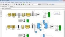
And also based on from whom I-- based on how I design it, I can also split it amongst the number of modules that I want. So with this, what I can do is I can very easily put together the powertrain of my two-wheeler. It did not be very detailed. So in this case, what I have done, I have two key subsystems here. The first one that I'm highlighting is the motor where I used the data, the tabulated torque-speed envelope, which I just showed you in my previous slide, 2 parameters.
So as you can see now, these are all steady state values. So we are, at this point, focusing on the steady state values. But still if we have some idea about the torque constant or time constant that the motor might have, we can use that and intelligently convert it to a dynamic model and get some more information out of it. I'll get into a little more detail of what are the other variants of motors we can have. But for the time being, for my analysis, I'm happy with this.
And now, that's the motor. Now I also found a few information in terms of the battery data sheet. So now the way we are going to parameterize is this-- so if you remember, we found out how many number of series and parallel combination that we need for our case. So now what I have done for the cell capacity that I need, I again went back to various different manufacturers websites and then found out the open circuit voltage against the And I have just used that.
Now sometimes you may also have some information in terms of thermal resistance. If you have, great, we can include that. But for the analysis, high level analysis that I'm doing, this is good enough. So with that, what I have also done, I have also added some accessory load onto the system.
So whatever my motor has, and based on the accessories that I have, I can also add additional power draw based on the motor and then feed it back to my battery. So eventually this simple battery block that I showed you, it internally will use a column counting method to tell me how much current it has lost or how the capacity is changing and based on that, give us a terminal voltage, which is being fed to my motor. So it's a very simple and sweet short powertrain model that we assembled.
Now we want to test it. So how do we test it? There are various ways. Now in this particular case, the way I have set up my motor, I can give a DART command to my motor and it will draw the-- it will make sure the rest of the system works.
But I didn't want to stop here. I want to expand it a bit. So what I did, I used that powertrain model and then added a few information in terms of what's my vehicle mass just to get some idea about to consider that fact as well, and put together this closed loop model.
Now what you are seeing here. So I have this motorcycle vehicle model. And within that, I have my pouch and whatever I showed you in my previous slide. And along with that, I also have this a motorcycle in plain block where I have defined the overall mass of my vehicle and a few other dimensional properties.
So this subsystem kind of covers that motorcycle vehicle, the overall planned model so to say, in terms of control system work. Now what I have also done, to test this model, I have created a few test scenarios. The first one, the topmost what you see, is a standard drive cycle. The idea is like we want to give a drive cycle, which is a good representation of what we see in our city.
We accelerate and then we brake quite a lot and rarely we have the opportunity to reach and stay at a high speed. But yeah, I mean this kind of captures that. And also, I had few other test cases. So for the other, I had three different test cases. And what I did was-- if you remember, that my motorcycle model, it wants the torque command, like how much torque I really want out of my system.
So to do that, I mean, of course, we can manually fit that value. But in my case, I decided to close the loop with the help of a longitudinal rider block. The idea is that this rider block will see what is the current speed and then what is the demand, and then try to generate the acceleration deceleration command. It is also possible to have gear shifting, but since we are talking electrical, so I have an electric motor, we don't have any gearshift mechanisms, I skipped that.
So this is at a high level, like what the rider is doing. Now you will also notice that I have a controller subsystem. Now what is this doing? Now we know that Prasanna briefly talked about that the mandate for having ABS, be it one channel or two channel, right?
So we can have all those things captured here. For the time being, what I have here is I have my simple motor control algorithm going on that and making sure that we get the demand that we are asking. So with that out of the way, there are quite a few other subsystems also that are there. We can talk about it towards the end.
But what I had proceeded on doing was I ran the model with the information that I had. And these are the few of the information that I got. So what you see here, if the streaming is good, you might be able to notice that there are quite a few different signals that I'm plotting against each other.
Now what the signals are, I have the reference signal that I have asked of that drive cycle. Then I have the CG speed. I also have the wheel speed for front and rear.
The reason I have put it in this way, so if there are any slippages going on, we can see that here. So we will see that either the wheel speeds are high or low, but the vehicle speed is lower than that. This is just for the presentation for us so that we can have more information on one plot.
Now the plots that you're seeing at the bottom-- we're looking at individual component level. So as for the motor, I have two plots going on here. So I'm looking into what is the torque that we will need for this demand, and also what is the current that we need to support this demand.
Then you are also looking at the battery pack. Now this is a very good sanity check of the amount of battery pack-- the capacity that is chosen. Is it good enough for the thing or do we need more? Do we need less? All right?
And also the supporting back voltages, and then back currents, then motor voltage, and overall motor speed. So now as you can see, we are at a point where we are now looking into each component and then trying to understand if we have done the right selection or can we do better. And one thing that you will also notice that while we were developing this powertrain model, we have put together a complete model which allows us to do this kind of optimization studies as well.
So as a logical step, we have some good starting points. But we would want to optimize because every single bit of range that we can get out of that is going to give us good competitive advantage. So what we can do with this model is that we can start working on maximizing the range. But maximizing the range is not going to come at a cost.
If we want to maximize the range, then we definitely have to control the power mode that you're running in the motor, and then our performance will come now, all right? So right now we will see that we have quite a few metrics that we have to look into which are opposing. So for example, the overall efficiency, the range, the performance, also battery cost.
Now we cannot just keep increasing our RPM rating. It is not only going to cost us more. There is a weight criteria that also comes in. So as you can see, if we take all these parameters and then try to set up an optimization, we can very easily create a good optimization problem segment out of that. For this example, I have the--
[AUDIO OUT]
--rating, number of cells, cells parallel, overall mass, and cost as a cost function.
So at the top, you will see some final results that I got. Now, one thing also I would like to highlight is that at this point of the time, if you remember the model complexity that we have chosen, they are quite simple. So for us, it will be very easy to change that component and then see for another and then see how this thing goes.
So that's a very good benefit that you can get. And all the whatever I have been showing you till this point can be fully automated as well. So once you have your model ready and you have it optimization ready, next time onwards you don't have to redo the same thing.
So we did that and post that. Then we saw some improvement and we saw a few increase in the cost. But the other improvements that we got was quite justified. So we went ahead with a few modified selections.
Great. So Abhisek--
Yes, Prasanna?
I just wanted to confirm my understanding so far. See, the first challenge that maybe if I am a two-wheeler designer, my first challenge was to build a vehicle level simulation. And now you just showed me how can I-- I can use that model that you showed, right, as a user? You'll be able to share that model with the user?
Yes. Yeah, that model is available.
So then that model can be used as a starting point model. They just have to customize it, parameterize it based on their parameterizations and build a vehicle level simulation model. I think it was clear that anyone can build his own drive cycle or his own test cycle for which he wants to test the vehicle for.
And then now the last point was with respect to range estimation or range optimization, not just range simulation. And then we can use numerical optimization capability of MATLAB. This is great. This is fine. But I think this--
[AUDIO OUT]
--not the drivetrain part of it. How about some of the other things like ride and handling or anti-lock braking systems? Can this model be scaled up to that also?
Yeah, that is a very good question, Prasanna. So to address Prasanna's question, if you remember for our powertrain portion, we just used the mass of the vehicle and just wanted to have some load on the system. But to be able to do these things, we still need some amount of vehicle dynamics to be incorporated.
Now since our last year matrix has added the capability of simulating the in-plane dynamics of two-wheeler, which means that not only longitudinal, you can also have the pitch motion. So the vehicle body block that I initially showed you, it is also capable to take information about how your vehicle body looks like in terms of, let's say, the various portions, like you will have your motorcycle body frame, then you will have your front steering then you will have your swingarm. So you can actually define those.
So you can say, OK, so this is my frame. This is where the CG is. And this is the total mass and moment of inertia. And if you do the same for all other components, for example, the swingarm, you define where the swingarm is defined and provide the associated mass and the CG, you'll be-- and along with the suspension, what you have in terms of front and the rear, you can very easily scale up that simplified longitudinal model to vehicle dynamics models. And the pitch motion can also come in.
Now here I am showing you a snapshot of how this parameterization would look like. And just to go over a few important ones, so you can see that I'm asking for my center of mass location of the frame. There are some initial conditions that we have defined. Now this is a new feature that you are seeing, which we introduced in the last release of MATLAB which was just a week before.
So if you have variables-- these are for something that people will first rate Simulink. So you would know that if you define a variable, it just stays there. And finding this value of this variable, you have to go to your MATLAB workspace and check. But that's no longer the case.
You can see that even if I have defined them as a variable, towards the right-hand side, the tool is now showing you what are the values for that. It can be scalar. It can be vector as well. So this is a very good indication.
I am also using this opportunity to show you what kind of parameterization one has to do if you are interested in this pitch motion. Now why is this pitch motion important? So if you are working with one channel or two channel levies system and while braking there is significant weight transfer that happens. And the grip level that changes is significant. So we need to consider that.
So to be able to do so, what we need to do is not only provide this mass and moment of inertia information, we will also have to provide the suspensions. Now this particular block, you can have a simplified suspension information. So you can just provide the overall ramping and stiffness value. Or if you want to have a complicated lookup table, if you have tested your suspension of course, you can use that. And you have a nonlinear suspension model as well to lookup table.
And now as you can understand, the people who are working for ride and handling kind of task, this is an important thing that you would want to do. Let's say if you are also tuning right now. But I'll come to that. Now if you focus on the ABS for the time being.
So I just defined my vehicle body. But another important aspect is also the tires. So now if you look into the tire subsystem, so what you will see is that we have the braking module and we also have the tire block itself. Now for the braking, you can define what is a static friction coefficient, kinetic friction of coefficient, and then the dimension of the brakes. The idea is that you will take the force and then multiply and convert that to moment.
And as for, the models that we have provided, they are all magic formula-based models. And if you have, let's say, some TIF files available with you for that, you can make use of those. But for the time being if you don't have any tire data, the data that we have provided, feel free to use that to get a representative idea of what's going on with the system. Yeah, but keep that in mind that having some sort of tire parameters with you will also help a lot.
Great. So I do the same thing for my rear wheel as well. So eventually what I did was I have some sort of contact models also that I've defined which kind of tells me like where the road and the wheels are meeting. OK, so now moving on.
So what I did, so we ran one test case. If you remember at the initial stage, I showed you three different test cases. The first one was a drive cycle. We talked about that till this point.
Now we also have another drive cycle where we are just reaching a maximum speed. And once we hit the maximum speed, we applied brakes completely. So what we're seeing here is that-- at the left-hand side, we have a very good animation which kind of also showed you what happened. I'll replay the video so that you can, again, see all the behaviors.
So the video is starting at the point where it has already reached and applying brakes. So what you will see is that my system is trying to brake. And it has some oscillatory--
[AUDIO OUT]
--it releases the brake, which you can see if you look at the brake pressure curve here. I'm using a laser pointer to highlight. I hope you can see it on the top right.
So here what you will see is that I have two different plots. I can do this as well. Yeah. So here you can see two different plots, OK?
The yellow one is the picture that was being applied in the front. And the blue one is the back. So you can clearly see the effect of weight transfer is also coming into the picture. And so to avoid locking, we have to distribute the brake forces as well.
So you can define your distribution, static distribution, or you can also have dynamic distribution based on the ride comfort you wish to provide. But we can see the whole effect. And if you look at the bottom plot, so remember, this is one plot that I showed you where I was comparing drive cycle along with CG along with the vehicle wheel speeds. This is how it helps.
[AUDIO OUT]
--been happening into the system. OK, so all those effects are being considered. And if you look at the few other plots in terms of the situation of the tires, so what you will see is that the front tire, so it lifts some speed, but then again it started oscillating. And then you can also see the slip values. And you can also check what is the brake torque.
So as you can see, now this can also help us with defining our brake actuators, and also try to understand if we are working at a safe range or the operating condition of the system. And you can size them as well based on how you want to consider. Now this is one use case where we are looking at the ABS. And the animation-- yeah, I skipped that portion.
But for the animation, what do you see on the left-hand side, we are using Unreal Engine based scenario to show you this visualization. At this point of the time, we are using it only for visualization. But MathWorks have the capability to equip, let's say, there is kind of sensors onto this vehicle. You can add radars. You can add lighters and other like ultrasound and all those things here and get a feeling of what's going on in the system.
So there are a few features that people are now talking about for high-end bikes, like we're calling them Advanced Rider Assistance System, ADAS. So in case like in the long run you wish to work on this kind of things, you can use the same model, which you developed and put obstacles or have some cornering and then see how it works so you can expand on that. But today, which is out of the scope, so I'll not get into much detail.
I'll show you another use case, however. This is a ride and handling analysis. And what I did is that right now, what you see is a straight route, but I have road humps. Now what I want to really see is how does it affect the overall vehicle condition and also like what kind of moments or forces that the rider is going to face.
So I initialize the vehicle at a very high speed. I kind of exaggerated it, but you can see. So this is kind of the road profile that I have taken. And you can see because the vehicle is going at a really high speed, around 50 or 60 kilometers per hour, so it's losing contact of the ground and then it is again regaining it, right? And it's quite a drastic motion that I have captured.
But I really wanted to show you the capabilities where you can see the effect of this road profile on your vehicle. And then we can see that it's now again braking. So the ABS portion is also coming in. But we have already seen that in the previous slide.
So what kind of information we can get out of it? The plot that I'm showing you is very busy, so let me explain it with the help of the magnifier. So what you're seeing here, the first plot, is that I have my tire locations, so the front tire and the rear tire. And you see there is a difference because of how the route profile was and then how the vehicle is.
Eventually, this kind of tells us where we have initialized the ground frame. And what we have in our vehicle, the one that I'm showing you, for the front I have forks, so you have linear springs there. And what you see is that I am showing the deformation, a linear deformation, and the forces that are being generated by the suspension.
So you can see that we're following the route profile nicely. And it's going other way and then trying to show us the effect of it. Now as for read, since we have a swingarm so I'm showing you the rear moments. And also, you can see that we're seeing the--
[AUDIO OUT]
--generated.
So now that would, of course, contribute to the vehicle pitch. So I am also plotting how the vehicle pitch rate was, and few other things like what is the actual pitch value in radians and how the average CG location has changed. So in addition to this, what I can also do is I can have some virtual sensors fitted at various portions of my vehicle body. And so those are all standard IMUs that we have, which you can parameterize and use to get some other information as well.
So this is something that you can make use of for your ride and handling. And with that information, you can use and modify the parameters. And let's say if you are tuning, and let's say, your chassi parameters that I initially showed you, those were all something that you can find from your CAD models if you have or from the design team. So you can fit in and then you can fiddle around with those.
[AUDIO OUT]
One quick question here. So I understood that initially you showed the audience how to do the powertrain design and the drive train design. And now you show the vehicle dynamics part of it, the ride and handling analysis, ABS analysis. So can you briefly say which all MathWorks products were used for building the first and the second model?
Yes, Prasanna, I'll do that. So the products that we used was a Pouch and Blockset. Support and Blockset was used for the initial portion where I was focusing only on the Pouch and aspects. Then the vehicle dynamics blockset where the longitudinal in-plane model of the vehicle dynamics was introduced and I brought them in.
So these are the two foundation toolboxes that you would need to be able to see this analysis that we have, right? Now, in addition to that, I will also show you towards the end, if time permits, is that we can also have a higher fidelity variant of the battery pack and motor pack.
Now this is a portion that we are going to go in elaborate in our tomorrow session. So you can have a look at that as well. But Prasanna, to answer that, yeah, those are the two toolboxes that I have used, along with the foundation like MATLAB, Simulink, and Stateflow.
Sure. Thanks, Abhisek.
But I think, Shripad, you do have the presenter rights, so if you can-- oh, it's back to me. OK, sure. I'll share again. Give me a minute. OK.
So in the meanwhile, we are getting a lot of questions. And as soon as Abhisek completes the technical part of it, we'll address the question and answers also.
Thanks, Prasanna. So one additional use case that I wanted to highlight is that we don't need to always go too complicated from the start itself. We can take step by step and slowly reach towards the end goal that we have in our plan. So here is one example from a customer named Ellio who developed a two-wheeler drive ebike using Simulink and a model-based design. And they used rapid prototyping a lot for tuning the controller.
So this is an approach that they have taken enough for them. They were able to create a vehicle model very quickly using a few of these techniques that I showed you today. And what they also found out, because of the simplicity of the system, they could very quickly prototype a controller by connecting to it using their laptop and quickly tune the parameters. And they do on vehicle prototyping and controller tuning as well.
And if you look at the results, the drive train model was developed in three months. And then they used it. And to prototype the controller, they had to use only one day. So they leveraged the full model-based design offerings that MathWorks has to get the maximum benefit of that.
So my colleagues are also posting a link to this user story where you can learn more in detail and where they explain about their challenges and how they address that. So I will encourage you to go and have a look at that. And if you find something interesting that you would want to adopt or you want to know more, please reach out to us. We'll be happy to help you.
Featured Product
Powertrain Blockset


Seleccione un país/idioma
Seleccione un país/idioma para obtener contenido traducido, si está disponible, y ver eventos y ofertas de productos y servicios locales. Según su ubicación geográfica, recomendamos que seleccione: United States.
También puede seleccionar uno de estos países/idiomas:
América
- América Latina (Español)
- Canada (English)
- United States (English)
Europa
- Belgium (English)
- Denmark (English)
- Deutschland (Deutsch)
- España (Español)
- Finland (English)
- France (Français)
- Ireland (English)
- Italia (Italiano)
- Luxembourg (English)
- Netherlands (English)
- Norway (English)
- Österreich (Deutsch)
- Portugal (English)
- Sweden (English)
- Switzerland
- United Kingdom (English)