5G NR Uplink Vector Waveform Generation
This example shows how to configure and generate a 5G NR uplink vector waveform with physical uplink shared channel (PUSCH) and sounding reference signal (SRS) for a baseband component carrier by using the nrWaveformGenerator function.
Introduction
This example shows how to parameterize and generate a 5G new radio (NR) uplink waveform by using the nrWaveformGenerator function. The generated waveform contains these channels and signals.
PUSCH and its associated demodulation reference signal (DM-RS) and phase-tracking reference signal (PT-RS)
SRS
The baseband component carrier waveform in this example is characterized by multiple subcarrier spacing (SCS) carriers and bandwidth parts (BWP), and multiple sequences of PUSCH and SRS transmission instances over the different BWPs. The example also shows how to parameterize and generate uplink control information (UCI) on PUSCH with CG-UCI and SRS for positioning.
For an example on how to generate a 5G uplink waveform with physical uplink control channel (PUCCH), see 5G NR Uplink with PUCCH Vector Waveform Generation.
Waveform and Carrier Configuration
Use the nrULCarrierConfig object to parameterize the baseband waveform generation. This object contains a set of additional objects associated with the waveform channels and signals and enables you to set these uplink carrier configuration parameters.
Label for this UL carrier configuration
SCS carrier bandwidth in resource blocks
Carrier cell ID
Length of the generated waveform in subframes
Windowing
Sample rate of the OFDM-modulated waveform
Carrier frequency for symbol phase compensation
You can control SCS carrier bandwidths and guardbands using the NStartGrid and NSizeGrid properties of the nrSCSCarrierConfig object.
waveconfig = nrULCarrierConfig;    % Create an uplink carrier configuration object
waveconfig.Label = 'UL carrier 1'; % Label for this uplink waveform configuration
waveconfig.NCellID = 0;            % Cell identity
waveconfig.ChannelBandwidth = 40;  % Channel bandwidth (MHz)
waveconfig.FrequencyRange = 'FR1'; % 'FR1' or 'FR2'
waveconfig.NumSubframes = 10;      % Number of 1 ms subframes in generated waveform (1, 2, 4, 8 slots per 1 ms subframe, depending on SCS)
waveconfig.WindowingPercent = 0;   % Percentage of windowing relative to FFT length
waveconfig.SampleRate = [];        % Sample rate of the OFDM-modulated waveform
waveconfig.CarrierFrequency = 0;   % Carrier frequency in Hz. This property is used for symbol phase
                                   % compensation before OFDM modulation

% Define a set of SCS-specific carriers, using the maximum sizes for a
% 40 MHz NR channel. See TS 38.101-1 for more information on defined
% bandwidths and guardband requirements.
scscarriers = {nrSCSCarrierConfig,nrSCSCarrierConfig};
scscarriers{1}.SubcarrierSpacing = 15;
scscarriers{1}.NSizeGrid = 216;
scscarriers{1}.NStartGrid = 0;

scscarriers{2}.SubcarrierSpacing = 30;
scscarriers{2}.NSizeGrid = 106;
scscarriers{2}.NStartGrid = 1;
BWPs
A BWP is formed by a set of contiguous resources sharing a numerology on a given SCS carrier. You can define multiple BWPs using a cell array. Each element in the cell array of nrWavegenBWPConfig objects defines a BWP. For each BWP, you can specify the SCS, the cyclic prefix (CP) length, and the bandwidth. The SubcarrierSpacing property links the BWP to one of the SCS specific carriers defined earlier. The NStartBWP property controls the location of the BWP in the carrier, relative to point A. NStartBWP is expressed in common resource blocks (CRB) in terms of the BWP numerology. Different BWPs can overlap with each other.

% BWP configurations
bwp = {nrWavegenBWPConfig,nrWavegenBWPConfig};
bwp{1}.BandwidthPartID = 1;        % BWP ID
bwp{1}.Label = 'BWP 1 @ 15 kHz';   % Label for this BWP
bwp{1}.SubcarrierSpacing = 15;     % BWP subcarrier spacing
bwp{1}.CyclicPrefix = 'Normal';    % BWP cyclic prefix for 15 kHz
bwp{1}.NSizeBWP = 25;              % Size of BWP in PRBs
bwp{1}.NStartBWP = 10;             % Position of BWP, relative to point A, in CRBs

bwp{2}.BandwidthPartID = 2;        % BWP ID
bwp{2}.Label = 'BWP 2 @ 30 kHz';   % Label for this BWP
bwp{2}.SubcarrierSpacing = 30;     % BWP subcarrier spacing
bwp{2}.CyclicPrefix = 'Normal';    % BWP cyclic prefix for 30 kHz
bwp{2}.NSizeBWP = 51;              % Size of BWP in PRBs
bwp{2}.NStartBWP = 40;             % Position of BWP, relative to point A, in CRBs
PUSCH Instances Configuration
Specify the set of PUSCH transmission instances in the waveform by using a cell array. Each element in the cell array of nrWavegenPUSCHConfig objects defines a sequence of PUSCH transmission instances. This example defines two PUSCH sequences that model two user equipment (UE) transmissions.
General Parameters
Set these parameters for each PUSCH sequence.
Enable or disable this PUSCH sequence.
Specify a label for this PUSCH sequence.
Specify the BWP carrying the PUSCH. The PUSCH uses the SCS specified for this BWP.
Power scaling in dB.
Enable or disable the UL-SCH transport channel coding.
RNTI.
NID for scrambling the PUSCH bits.
Transform precoding. When transform precoding is
true, the transform precoding is enabled and the resultant waveform is DFT-s-OFDM. When transform precoding isfalse, the resultant waveform is CP-OFDM.Target code rate used to calculate the transport block sizes.
Overhead parameter.
Transmission scheme. When the transmission scheme is
'codebook', the MIMO precoding is enabled and a precoding matrix is selected based on the number of layers, number of antenna ports and the transmitted precoding matrix indicator. When the transmission is set to'nonCodebook', an identity matrix is used, leading to no MIMO precoding.Symbol modulation.
Number of layers. The number of layers is restricted to a maximum of 4 in uplink as there is only one code word transmission. Nominally, the number of layers is set to 1 when transform precoding is enabled. This value is ignored, when the
DMRS.PortSetproperty is specified.Number of antenna ports. It is used when codebook transmission is enabled. The number of antenna ports must be greater than or equal to number of DM-RS ports configured.
Transmitted precoding matrix indicator.
Redundancy version (RV) sequence.
Frequency hopping.
Resource block offset for second hop.
Transport block data source. You can use an array of bits or one of these standard PN sequences:
'PN9-ITU','PN9','PN11','PN15','PN23'. You can specify the seed for the generator as a cell array in the form{'PN9', seed}. If you do not specify a seed, the generator is initialized with all ones.
pusch = {nrWavegenPUSCHConfig};           % Create a PUSCH configuration object for the first UE
pusch{1}.Enable = 1;                      % Enable PUSCH sequence
pusch{1}.Label = 'UE 1 - PUSCH @ 15 kHz'; % Label for this PUSCH sequence
pusch{1}.BandwidthPartID = 1;             % BWP of PUSCH transmission
pusch{1}.Power = 0;                       % Power scaling in dB
pusch{1}.Coding = 1;                      % Enable the UL-SCH transport channel coding
pusch{1}.NID = 1;                         % Scrambling for data part
pusch{1}.RNTI = 11;                       % RNTI for the first UE
pusch{1}.TransformPrecoding = false;      % Transform precoding
pusch{1}.TargetCodeRate = 0.47;           % Code rate used to calculate transport block sizes
pusch{1}.XOverhead = 0;                   % Rate matching overhead

% Transmission settings
pusch{1}.TransmissionScheme = 'codebook'; % 'codebook','nonCodebook'
pusch{1}.Modulation = 'QPSK';             % 'pi/2-BPSK','QPSK','16QAM','64QAM','256QAM'
pusch{1}.NumLayers = 2;                   % Number of PUSCH layers
pusch{1}.NumAntennaPorts = 4;             % Number of antenna ports
pusch{1}.TPMI = 0;                        % Transmitted precoding matrix indicator (0...27)
pusch{1}.RVSequence = [0 2 3 1];          % RV sequence to be applied cyclically across the PUSCH allocation sequence
pusch{1}.FrequencyHopping = 'interSlot';  % Frequency hopping configuration
pusch{1}.SecondHopStartPRB = 10;          % Resource block offset for second hop

% Data source
pusch{1}.DataSource = 'PN9';              % Channel data source
Allocation
This figure shows the parameters of the PUSCH allocation.

You can set these parameters to control the PUSCH allocation. These parameters are relative to the BWP.
PUSCH mapping type.
Symbols in a slot allocated to each PUSCH instance. For PUSCH mapping type
'A', the start symbol within a slot must be zero and the length can be from 4 to 14 (for normal CP) and up to 12 (for extended CP). For PUSCH mapping type'B', the start symbol can be from any symbol in the slotSlots in a frame used for the sequence of PUSCH.
Period of the allocation in slots. Empty period indicates no repetition of the slot pattern.
The allocated PRBs relative to the BWP.
pusch{1}.MappingType = 'A';         % PUSCH mapping type ('A'(slot-wise),'B'(non slot-wise))
pusch{1}.SymbolAllocation = [0 14]; % First symbol and length
pusch{1}.SlotAllocation = [0 1];    % Allocated slots indices for PUSCH sequence
pusch{1}.Period = 5;                % Allocation period in slots
pusch{1}.PRBSet = 0:10;             % PRB allocation
PUSCH DM-RS Configuration
Set the DM-RS parameters.
% Antenna port and DM-RS configuration (TS 38.211 section 6.4.1.1)
pusch{1}.DMRSPower = 0;                    % Additional power boosting in dB

pusch{1}.DMRS.DMRSConfigurationType = 1;   % DM-RS configuration type (1,2)
pusch{1}.DMRS.NumCDMGroupsWithoutData = 2; % Number of DM-RS CDM groups without data. The value can be one of the set {1,2,3}
pusch{1}.DMRS.DMRSPortSet = [0 2];         % DM-RS antenna ports used ([] gives port numbers 0:NumLayers-1)
pusch{1}.DMRS.DMRSTypeAPosition = 2;       % Mapping type A only. First DM-RS symbol position (2,3)
pusch{1}.DMRS.DMRSLength = 1;              % Number of front-loaded DM-RS symbols (1(single symbol),2(double symbol))
pusch{1}.DMRS.DMRSAdditionalPosition = 2;  % Additional DM-RS symbol positions (max range 0...3)
pusch{1}.DMRS.NIDNSCID = 1;                % Scrambling identity for CP-OFDM (0...65535). Use empty ([]) to use physical layer cell identity
pusch{1}.DMRS.NSCID = 0;                   % Scrambling initialization for CP-OFDM (0,1)
pusch{1}.DMRS.NRSID = 0;                   % Scrambling identity for DFT-s-OFDM DM-RS (0...1007). Use empty ([]) to use physical layer cell identity

pusch{1}.DMRS.GroupHopping = true;         % Group hopping configuration. This property is used only when transform precoding is enabled
pusch{1}.DMRS.SequenceHopping = false;     % Sequence hopping configuration. This property is used only when transform precoding is enabled
The GroupHopping property is used in DM-RS sequence generation when transform precoding is enabled. You can set GroupHopping to:
'enable'to indicate the presence of group hopping. It is configured by higher-layer parametersequenceGroupHopping.'disable'to indicate the presence of sequence hopping. It is configured by higher-layer parametersequenceHopping.'neither'to indicate both group hopping and sequence hopping are not present.
The number of DM-RS CDM groups without data depends on the configuration type. The maximum number of DM-RS CDM groups can be 2 for DM-RS configuration type 1 and it can be 3 for DM-RS configuration type 2.
PUSCH PT-RS Configuration
Set the PT-RS parameters.
% PT-RS configuration (TS 38.211 section 6.4.1.2)
pusch{1}.EnablePTRS = 0;            % Enable or disable the PT-RS (1 or 0)
pusch{1}.PTRSPower = 0;             % Additional PT-RS power boosting in dB for CP-OFDM

pusch{1}.PTRS.TimeDensity = 1;      % Time density (L_PT-RS) of PT-RS (1,2,4)
pusch{1}.PTRS.FrequencyDensity = 2; % Frequency density (K_PT-RS) of PT-RS for CP-OFDM (2,4)
pusch{1}.PTRS.NumPTRSSamples = 2;   % Number of PT-RS samples (NGroupSamp) for DFT-s-OFDM (2,4)
pusch{1}.PTRS.NumPTRSGroups = 2;    % Number of PT-RS groups (NPTRSGroup) for DFT-s-OFDM (2,4,8)
pusch{1}.PTRS.REOffset = '00';      % PT-RS resource element offset for CP-OFDM ('00','01','10','11')
pusch{1}.PTRS.PTRSPortSet = 0;      % PT-RS antenna ports must be a subset of DM-RS ports for CP-OFDM
pusch{1}.PTRS.NID = 0;              % PT-RS scrambling identity for DFT-s-OFDM (0...1007)
When PT-RS is enabled for CP-OFDM, the DM-RS ports must be in the range from 0 to 3 for DM-RS configuration type 1, and in the range from 0 to 5 for DM-RS configuration type 2. When PT-RS is enabled for DFT-s-OFDM and the number of PT-RS groups is set to 8, the number of PT-RS samples must be set to 4.
UCI on PUSCH
You can set these parameters to configure the transmission of UCI on PUSCH.
Enable or disable the transmission of HARQ-ACK, CSI part 1, CSI part2, and CG-UCI
Number of HARQ-ACK, CSI part 1, CSI part 2, and CG-UCI bits.
BetaOffsetACK,BetaOffsetCSI1,BetaOffsetCSI2, andBetaOffsetCGUCIcan be set from the tables 9.3-1 and 9.3-2 of TS 38.213.Data source for HARQ-ACK, CSI part 1, CSI part 2, and CG-UCI. You can use an array of bits or one of these standard PN sequences:
'PN9-ITU','PN9','PN11','PN15','PN23'. You can specify the seed for the generator as a cell array in the form{'PN9', seed}. If you do not specify a seed, the generator is initialized with all ones.Enable UL-SCH transmission with UCI.
UCIScalingis provided by higher layer parameterscaling, as per TS 38.212, Section 6.3.2.4.
pusch{1}.EnableACK = true;        % Enable or disable HARQ-ACK
pusch{1}.NumACKBits = 5;          % Number of HARQ-ACK bits
pusch{1}.BetaOffsetACK = 1;       % Power factor of HARQ-ACK
pusch{1}.DataSourceACK = 'PN9';   % HARQ-ACK data source
pusch{1}.EnableCSI1 = true;       % Enable or disable CSI part 1
pusch{1}.NumCSI1Bits = 10;        % Number of CSI part 1 bits
pusch{1}.BetaOffsetCSI1 = 2;      % Power factor of CSI part 1
pusch{1}.DataSourceCSI1 = 'PN9';  % CSI part 1 data source
pusch{1}.EnableCSI2 = true;       % Enable or disable CSI part 2
pusch{1}.NumCSI2Bits = 10;        % Number of CSI part 2 bits
pusch{1}.BetaOffsetCSI2 = 2;      % Power factor of CSI part 2
pusch{1}.DataSourceCSI2 = 'PN9';  % CSI part 2 data source
pusch{1}.EnableCGUCI = false;     % Enable or disable CG-UCI
pusch{1}.NumCGUCIBits = 10;       % Number of CG-UCI bits
pusch{1}.BetaOffsetCGUCI = 2;     % Power factor of CG-UCI
pusch{1}.DataSourceCGUCI = 'PN9'; % CG-UCI data source
pusch{1}.EnableULSCH = true;      % Enable or disable UL-SCH when there is UCI transmission on PUSCH
pusch{1}.UCIScaling = 1;          % Scaling factor (0.5, 0.65, 0.8, 1)
When both HARQ-ACK and CG-UCI are enabled, Section 6.3.2.1.4 of TS 38.212 specifies the UCI bit sequence as the union of the CG-UCI bits and the HARQ-ACK bits. Therefore, the processing of UCI on PUSCH considers any active CG-UCI source as an extension to HARQ-ACK and only the value of BetaOffsetACK is used in this case.
Specifying Multiple PUSCH Sequences
Specify the second PUSCH sequence for the second BWP.
pusch{2} = pusch{1};                 % Create a PUSCH configuration object for the second UE
pusch{2}.Enable = 1;
pusch{2}.Label = 'UE 2 - PUSCH @ 30 kHz';
pusch{2}.BandwidthPartID = 2;        % PUSCH mapped to the second BWP
pusch{2}.RNTI = 12;                  % RNTI for the second UE
pusch{2}.SymbolAllocation = [0 12];
pusch{2}.SlotAllocation = [5 6 7 8];
pusch{2}.PRBSet = 5:10;              % PRB allocation, relative to BWP
pusch{2}.Period = 10;
pusch{2}.TransformPrecoding = 1;
pusch{2}.FrequencyHopping = 'interSlot';
pusch{2}.NumLayers = 1;
pusch{2}.RNTI = 1;

pusch{2}.DMRS.GroupHopping = false;
pusch{2}.DMRS.DMRSPortSet = 1;
SRS Instances Configuration
Specify SRS in the waveform. Each element in the cell array of nrWavegenSRSConfig objects defines a sequence of SRS instances associated with a BWP. Define two disabled SRS sequences.
General Parameters
Set these parameters for each SRS sequence.
Enable or disable this SRS sequence.
Specify a label for this SRS sequence.
Specify the BWP carrying this SRS sequence. The SRS sequence configuration uses the SCS specified for this BWP.
Specify the power scaling in dB.
srs = {nrWavegenSRSConfig};
srs{1}.Enable = 0;
srs{1}.Label = 'SRS @ 15 kHz';
srs{1}.BandwidthPartID = 1;
srs{1}.Power = 3; % Power scaling in dB
SRS Configuration
You can configure these parameters for each SRS sequence.
Number of SRS antenna ports.
Symbols in a slot allocated to each SRS sequence.
Slots within a period used for SRS transmission.
Period of the allocation in slots. Empty period indicates no repetition of the slot pattern.
Starting position of the SRS sequence in the BWP in RBs.
Additional frequency offset from the starting position in 4-PRB blocks.
Bandwidth and frequency hopping configuration. The occupied bandwidth depends on the properties
CSRS,BSRS, andBHop. SetBHop < BSRSto enable frequency hopping.Transmission comb to specify the SRS frequency density in subcarriers.
Offset of the transmission comb in subcarriers.
Cyclic shift rotating the low-PAPR base sequence. The maximum number of cyclic shifts, 8 or 12, depends on the transmission comb number, 2 or 4. For 4 SRS antenna ports, the subcarrier set allocated to the SRS in the first and third antenna ports depends on the cyclic shift.
Number of repeated SRS symbols within a slot. It disables frequency hopping in blocks of
Repetitionsymbols. SetRepetition = 1for no repetition.Group or sequence hopping. It can be
'neither','groupHopping'or'sequenceHopping'.Scrambling identity. It initializes the pseudo-random binary sequence when group or sequence hopping are enabled.
srs{1}.NumSRSPorts = 1;             % Number of SRS ports (1,2,4)
srs{1}.NumSRSSymbols = 4;           % Number of SRS symbols in a slot (1,2,4)
srs{1}.SymbolStart = 10;            % Time-domain position of the SRS in the slot. (8...13) for normal CP and (6...11) for extended CP
srs{1}.SlotAllocation = 2;          % Allocated slots indices
srs{1}.Period = 5;                  % Allocation period in slots
srs{1}.FrequencyStart = 0;          % Frequency position of the SRS in BWP in RBs
srs{1}.NRRC = 0;                    % Additional offset from FreqStart specified in blocks of 4 PRBs (0...67)
srs{1}.CSRS = 13;                   % Bandwidth configuration C_SRS (0...63). It controls the allocated bandwidth to the SRS
srs{1}.BSRS = 2;                    % Bandwidth configuration B_SRS (0...3). It controls the allocated bandwidth to the SRS
srs{1}.BHop = 1;                    % Frequency hopping configuration (0...3). Set BHop < BSRS to enable frequency hopping
srs{1}.KTC = 2;                     % Comb number (2,4). It indicates the allocation of the SRS every KTC subcarriers
srs{1}.KBarTC = 0;                  % Subcarrier offset of the SRS sequence (0...KTC-1)
srs{1}.CyclicShift = 0;             % Cyclic shift number (0...NCSmax-1). NCSmax = 8 for KTC = 2 and NCSmax = 12 for KTC = 4.
srs{1}.Repetition = 1;              % Repetition factor (1,2,4). It indicates the number of equal consecutive SRS symbols in a slot
srs{1}.GroupSeqHopping = 'neither'; % Group or sequence hopping ('neither', 'groupHopping', 'sequenceHopping')
srs{1}.NSRSID = 0;                  % Scrambling identity (0...1023)
srs{1}.SRSPositioning = false;      % Enable SRS for user positioning
Specifying Multiple SRS Sequences
Specify the second SRS sequence for the second BWP.
srs{2} = srs{1};
srs{2}.Enable = 0;
srs{2}.Label = 'SRS @ 30 kHz';
srs{2}.BandwidthPartID = 2;
srs{2}.NumSRSSymbols = 2;
srs{2}.SymbolStart = 12;
srs{2}.SlotAllocation = [5 6 7 8];
srs{2}.Period = 10;
srs{2}.BSRS = 0;
srs{2}.BHop = 0;
Waveform Generation
Assign all the channel and signal parameters to the main carrier configuration object nrULCarrierConfig, then generate and plot the waveform.
waveconfig.SCSCarriers = scscarriers;
waveconfig.BandwidthParts = bwp;
waveconfig.PUSCH = pusch;
waveconfig.SRS = srs;

% Generate complex baseband waveform
[waveform,info] = nrWaveformGenerator(waveconfig);
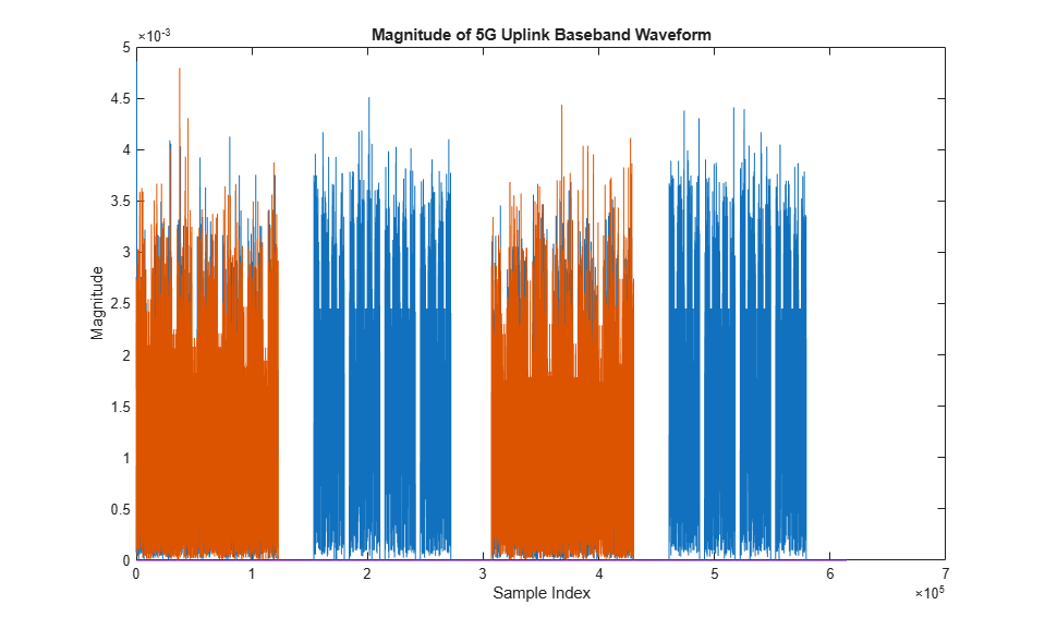
Plot the magnitude of the baseband waveform for the set of antenna ports defined.
figure;
plot(abs(waveform));
title('Magnitude of 5G Uplink Baseband Waveform');
xlabel('Sample Index');
ylabel('Magnitude');
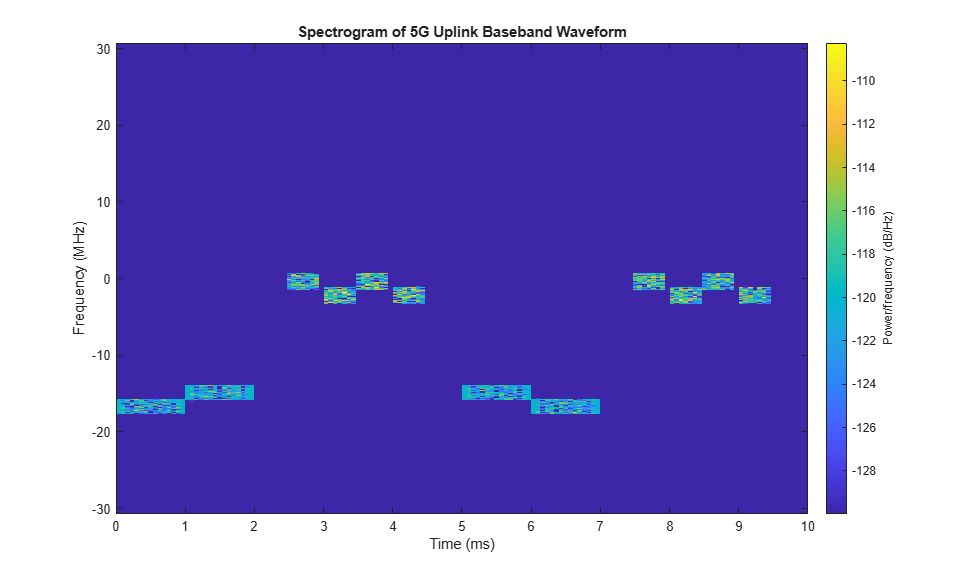
Plot the spectrogram of the waveform for the first antenna port.
samplerate = info.ResourceGrids(1).Info.SampleRate;
nfft = info.ResourceGrids(1).Info.Nfft;
figure;
spectrogram(waveform(:,1),ones(nfft,1),0,nfft,'centered',samplerate,'yaxis','MinThreshold',-130);
title('Spectrogram of 5G Uplink Baseband Waveform');
The waveform generator function returns the time-domain waveform and a structure info. The info structure contains the underlying resource element grid and a breakdown of the resources that all the PUSCH and SRS instances use in the waveform.
The ResourceGrids field is a structure array, which contains these fields.
The resource grid corresponding to each BWP.
The resource grid of the overall bandwidth containing the channels and signals in each BWP.
An info structure with information corresponding to each BWP. For example, display the information of the first BWP.
disp('Modulation information associated with BWP 1:')
disp(info.ResourceGrids(1).Info)
Modulation information associated with BWP 1:
                   Nfft: 4096
             SampleRate: 61440000
    CyclicPrefixLengths: [320 288 288 288 288 288 288 320 288 … ] (1×14 double)
          SymbolLengths: [4416 4384 4384 4384 4384 4384 4384 … ] (1×14 double)
              Windowing: 0
           SymbolPhases: [0 0 0 0 0 0 0 0 0 0 0 0 0 0]
         SymbolsPerSlot: 14
       SlotsPerSubframe: 1
          SlotsPerFrame: 10
                     k0: 0

The generated resource grid is a 3-D matrix. The different planes in the grid represent the antenna ports in increasing port number order.