comm.gpu.PSKDemodulator
(To be removed) Demodulate signals using M-ary PSK method with GPU
comm.gpu.PSKDemodulator will be removed in a future release. Use pskdemod instead. (since R2026a) For
information on updating your code, see Version History.
Description
The comm.gpu.PSKDemodulator object demodulates a signal that was modulated using
the M-ary phase shift keying (M-PSK) method implemented on a graphics processing unit
(GPU). The input is a baseband representation of the modulated signal.
To demodulate a signal that was modulated using the M-PSK method:
Create the
comm.gpu.PSKDemodulatorobject and set its properties.Call the object with arguments, as if it were a function.
To learn more about how System objects work, see What Are System Objects?
Creation
Syntax
Description
gpumpskdemod = comm.gpu.PSKDemodulator creates a
GPU-based demodulator System object™ that demodulates the input signal using the M-PSK method.
gpumpskdemod = comm.gpu.PSKDemodulator(
sets properties using one or more name-value arguments. For example,
Name=Value)comm.gpu.PSKDemodulator(DecisionMethod="Hard decision")
specifies demodulation using the hard-decision method.
gpumpskdemod = comm.gpu.PSKDemodulator(M,phase,
sets the Name=Value)ModulationOrder
property to M, sets the PhaseOffset property
to phase, and sets optional name-value arguments. Specify
phase in radians.
Properties
Usage
Description
y = gpumpskdemod(x,var)var. This
syntax applies when you set the BitOutput property to
true, the DecisionMethod
property to 'Approximate log-likelihood ratio' or
'Log-likelihood ratio', and the VarianceSource
property to 'Input port'.
Input Arguments
Output Arguments
Object Functions
To use an object function, specify the
System object as the first input argument. For
example, to release system resources of a System object named obj, use
this syntax:
release(obj)
Examples
More About
The signal preprocessing required for BPSK demodulation depends on the configuration.
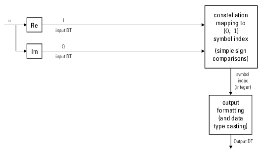
This figure shows the hard-decision BPSK demodulation signal diagram for the trivial phase offset (multiple of π/2) configuration.
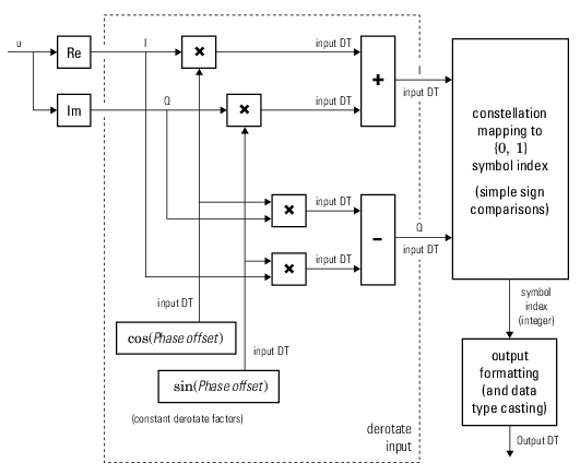
This figure shows the hard-decision BPSK demodulation floating-point signal diagram for the nontrivial phase offset configuration.
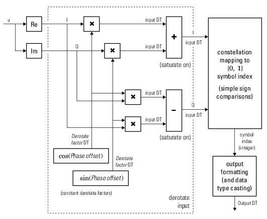
This figure shows the hard-decision BPSK demodulation fixed-point signal diagram for the nontrivial phase offset configuration.
The signal preprocessing required for QPSK demodulation depends on the configuration.
This figure shows the hard-decision QPSK demodulation signal diagram for the trivial phase offset (odd multiple of π/4) configuration.

This figure shows the hard-decision QPSK demodulation floating-point signal diagram for the nontrivial phase offset configuration.

This figure shows the hard-decision QPSK demodulation fixed-point signal diagram for the nontrivial phase offset configuration.

The signal preprocessing required for higher order PSK demodulation depends on the configuration.
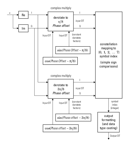
This figure shows the hard-decision 8-PSK demodulation signal diagram for the trivial phase offset (odd multiple of π/8) configuration.
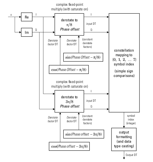
This figure shows the hard-decision 8-PSK demodulation fixed-point signal diagram for trivial phase offset (odd multiple of π/8) configuration.
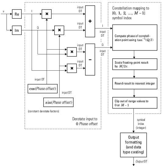
This figure shows the hard-decision M-PSK demodulation floating-point signal diagram for the nontrivial phase offset configuration.
For M > 8, to improve speed and implementation costs, no derotation arithmetic is performed for trivial case (specifically, when phase offset is 0, π/2, π, or 3π/2).
Also, for M > 8, only double and
single input types are supported.
Tips
To use this object, you must install Parallel Computing Toolbox™ and have access to a supported GPU. If the host computer has a GPU configured, processing uses the GPU. Otherwise, processing uses the CPU. For more information about GPUs, see GPU Computing (Parallel Computing Toolbox).
References
[1] Proakis, John G. Digital Communications. 4th ed. New York: McGraw Hill, 2001.
Extended Capabilities
Version History
Introduced in R2012aSee Also
Functions
Objects
gpuArray(Parallel Computing Toolbox)
Blocks
Topics
- Functions and System Objects Supporting GPU Arrays
- GPU Computing (Parallel Computing Toolbox)
- Accelerate Simulation Using GPUs