cdma2000 Physical Layer in Simulink
This example demonstrates how the Communications Toolbox™ can be used for: (i) working with standard-compliant cdma2000® waveforms in Simulink® and (ii) building standard-compliant decoder subsystems. Specifically, the model mainly covers the Forward Fundamental Channel (F-FCH) of the downlink channel between a base station and a mobile station for radio configuration 3 and spreading rate 1.
Introduction
cdma2000 is a terrestrial radio interface for the third generation of wireless communications developed within the framework of the International Mobile Telecommunications (IMT)-2000 standard, as defined by the International Telecommunication Union (ITU). The specifications of the cdma2000 system are being developed by the Third Generation Partnership Project 2 (3GPP2).
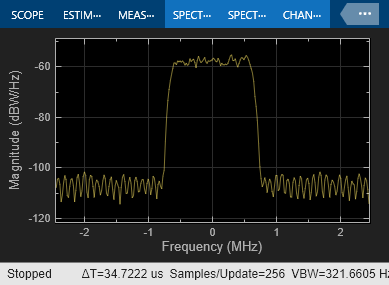
The cdma2000 air interface is a direct spread technology. This means that it spreads encoded user data at a relatively low rate over a much wider bandwidth (1.23 MHz for the 1x case), using a sequence of pseudo-random units called chips at a much higher rate (1.2288 Mcps). By assigning a unique code to each user, the receiver, which has knowledge of the code of the intended user, can successfully separate the desired signal from the received waveform.
Structure of the Example
The key components of the forward cdma2000 physical layer are the transmitting base station, the channel, and the mobile station (receiver).
The base station is represented by a standard-compliant forward waveform, which is generated with the
cdma2000ForwardWaveformGeneratorfunction and is imported from the MATLAB® Workspace.The channel can function as a SISO Fading Channel, an AWGN Channel, or as an empty subsystem.
The mobile receiver includes the decoder and receiver subsystem, which perform all operations needed for decoding the standard-compliant waveform.

Parameters in the Model
A configuration block labeled "Model Parameters" enables you to configure the generated waveform, as well as the channel model.
Base Station
For waveform generation, you can customize the data rate, the oversampling ratio, the QOF index and the Walsh code. Every customization regenerates a standard-compliant waveform in the MATLAB Workspace. The waveform generation performs the following steps:
Generating a PN9 bit sequence
Inserting frame quality indicator bits (CRC)
Appending tail bits before coding
Convolutional encoding
Repetition
Puncturing
Block interleaving
Mapping and scaling
Spreading by a Walsh code
Spreading by a QOF (quasi-orthogonal function) mask
Walsh code rotation
Quadrature scrambling by a PN (pseudonoise) sequence
Transmit filtering by an oversampled square root raised cosine filter
Channel
The default channel model includes the effects of both multipath Rayleigh fading and additive white Gaussian noise. Alternatively, you can use the channel as a source of Gaussian noise only, or as an empty subsystem. You can configure the channel characteristics using the Model Parameters block in the top left corner of the model.
Receiver
The most important parts of the receiver subsystem are the Rake receiver and the channel estimator.
Besides these two components,the other receiver operations are straightforward inverses of some waveform-generation operations.
Decoder
The decoder subsystem conducts the inverse operations of the remaining waveform-generation operations.
Results and Displays
The BER Calculation component compares the decoded signal with the signal of the data source. BER equals zero under all possible configurations for waveform generation, assuming no changes have been made to the model. Notice that signal delay is properly handled and frames are aligned.
To view data graphically, open the scopes by double-clicking the Open Scopes icon. The scopes show the following information:
The 'Tx Waveform: Spectrum' scope shows the power spectrum of the generated waveform.

The 'Tx Waveform: Constellation' scope shows the generated waveform in the I-Q plane. The transmitted signal seems scattered, as a result of spreading.
The 'From Channel' spectrum scope noticeably illustrates the effects of the channel on the received signal.

The 'From Channel' constellation scope shows the I-Q output of the channel. The signal is still spread.
The 'After Derotation' constellation scope shows the data after the receiver subsystem has despread the signal and compensated for the phase rotation caused by the channel. The signal still suffers from some effects of the multipath fading channel.
The 'After Rake' constellation scope shows the output of the rake receiver after the rake receiver has compensated for the attenuation caused by the channel. Even though some bit errors may exist at this stage, these are later on corrected by a powerful decoding operation.
Simulink Techniques Illustrated in the Example
In addition to illustrating a cdma2000 application, this example also illustrates several techniques for modeling in Simulink. In particular, this example shows how you can:
1. Use the Communications Toolbox extensively to implement wireless systems.
2. Represent the architecture of the design using subsystems.
3. Import signals from the MATLAB Workspace.
4. Reuse and share custom-built blocks using a library. To view the library for this example, double-click the cdma2000 Library icon in the top right corner of model.
5. Control the parameters of the simulation using a configuration dialog box.
6. Handle end-to-end delays and perform frame alignment.
Selected Bibliography
[1] C.S0002-F v2.0: Physical Layer Standard for cdma2000 Spread Spectrum Systems.
[2] E.G. Tiedemann, "cdma2000 1X: New Capabilities for CDMA Networks," IEEE Vehicular Technology Society News, vol. 48, no. 4, pp. 4-12, Nov. 2001.
[3] TIA/EIA/IS-2000.2-A, Physical Layer Standard for cdma2000 Spread Spectrum Systems, Telecommunications Industry Association, Arlington, VA, March 2000.