Estimate Distance Between USRP Radios Using Time of Arrival Algorithm
This example shows how to estimate the distance between two USRP™ radios by measuring signal time of flight (ToF) using the time of arrival (ToA) algorithm. To improve accuracy, you measure ToF in both directions.
ToA localizes and tracks objects by measuring the absolute arrival time of a signal at one or more spatially separated receivers. It relies on the signal’s travel time from transmitter to receiver and requires precise time synchronization between devices. ToA supports several real-time localization and positioning algorithms. The system multiplies the measured time by the speed of light to calculate the range to each receiver. It then combines ranges from multiple receivers to perform trilateration and determine the object’s position.
Required Hardware and Software
To run this example, you need:
Two USRP radios with GPSDO modules.
200-Series USRP Radio (B2xx) and Communications Toolbox Support Package for USRP Radio. For information on supported radios, see Supported Hardware and Required Software.
300-Series USRP Radio (X3xx) and Wireless Testbench Support Package for NI USRP Radios. For information on how to map an NI USRP device to an Ettus Research 300-series USRP device, see Supported Radio Devices (Wireless Testbench).
Two GPS antennas.
Two directional antennas.
Hardware Setup
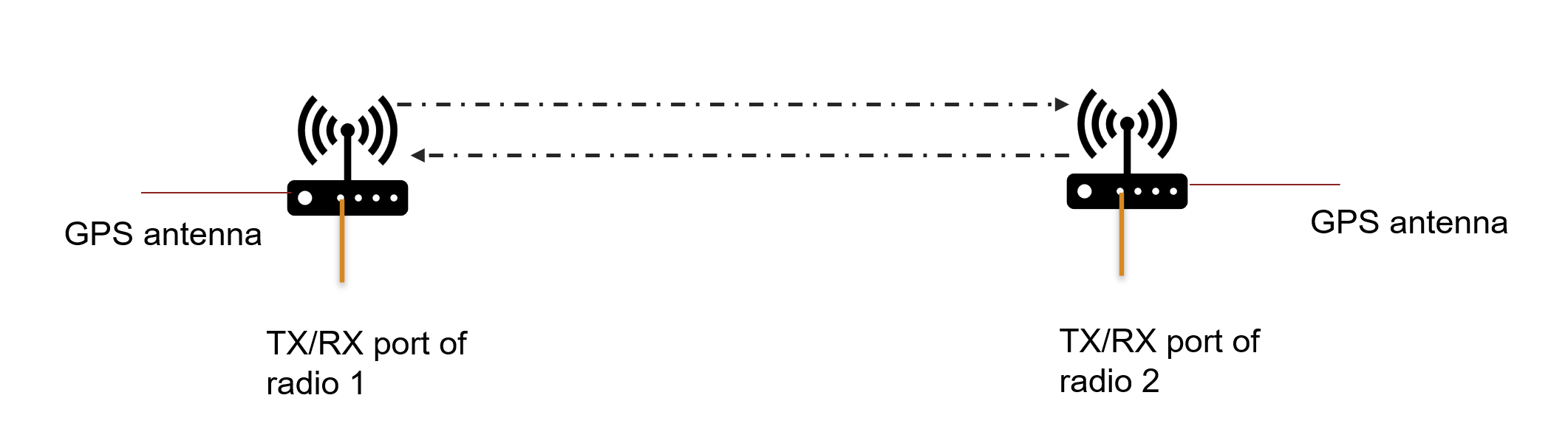
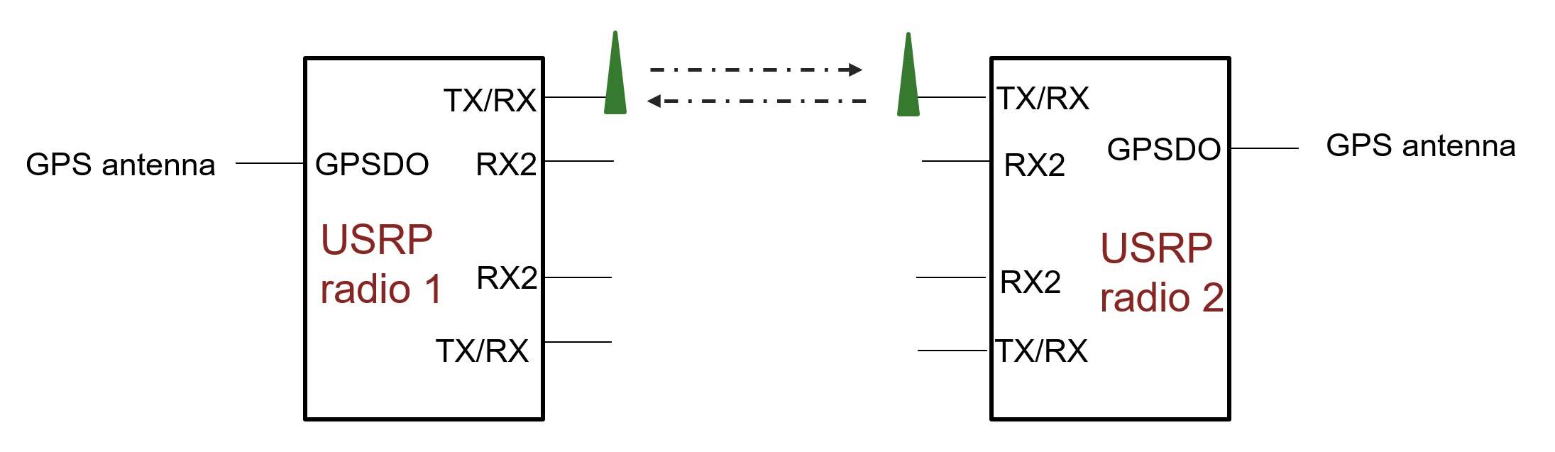
Connect two USRP radios equipped with GPSDO modules and GPS antennas facing the sky. Make sure that both radios are locked to a GPS signal for global time synchronization. Attach a directional antenna to the TX/RX port of each radio for transmission and reception. This configuration allows the setup to work with only two antennas instead of four.
Introduction
Connect two USRP radios and synchronize them to a GPS clock source.
Trigger transmission and reception on both radios at a specific time.
Transmit a known sequence or message from one radio to the other. Use the same gold sequence on both the radios.
Perform cross-correlation on the received sequence with the known sequence.
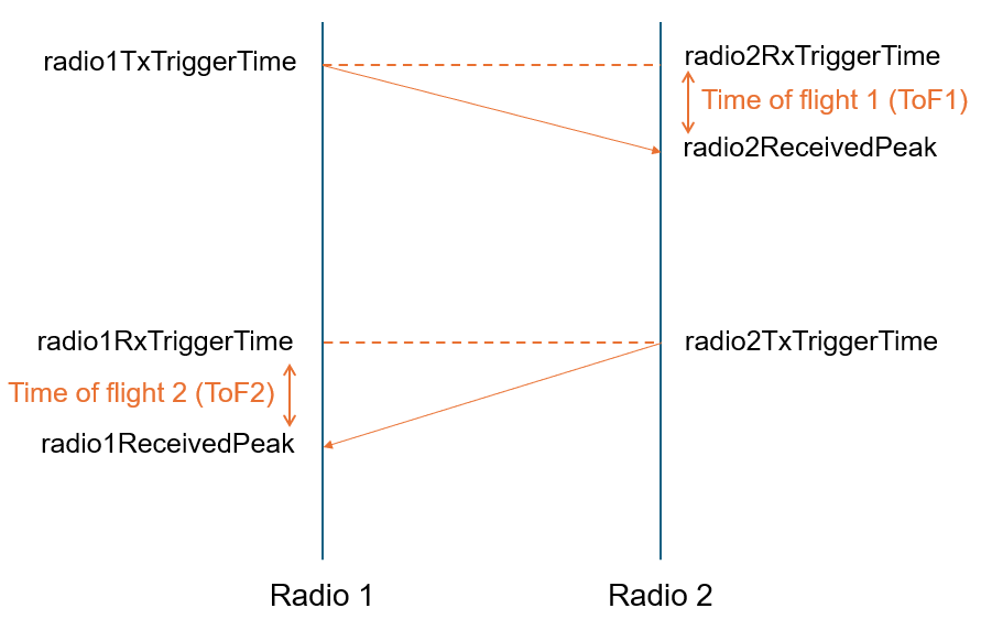
Identify the time at which the correlation peak occurs and compute the difference from the trigger time as Time of Flight (ToF1).
Repeat the process in the opposite direction (second radio to first radio).
Compute the ToF as the average value of both computed times of flight.
The example mainly consists of two procedures:
Reference Measurement (radios close together,
referenceCalculation = true)Actual Measurement (radios at unknown distance,
referenceCalculation = false)
The reference measurement is necessary to estimate the hardware offset. Once this offset is determined, it can be subtracted from all subsequent measurements taken at unknown distances.
To measure an unknown distance, first set up the hardware and synchronize the radios to a GPS signal. Next, configure the necessary parameters and trigger times in MATLAB. For the reference measurement at zero distance, run the two scripts: EstimateDistanceBetweenUSRPRadiosUsingTOAExample.m and helperRadio2ConfigurationForTOA.m. Save the resulting time-of-flight (ToF) data for reference (stored in the referenceData.mat files).
Afterward, move the radios to the location with the unknown distance. Update the trigger times as needed, disable the referenceCalculation flag (in both the files), and run both scripts again. Finally, calculate the unknown distance using the measured ToFs and the previously saved reference ToFs.
Configure Radio:
This example requires two different scripts running on two MATLAB sessions either on same or different machines.
You configure radio 1 with platform, serial number or IP address, gain, center frequency, sample rate, and trigger times for transmit and receive. Use the same values for radio 2 in helperRadio2ConfigurationforToA script. For more information on available radios on your computer, use findsdr function.
platform ="B210"; address =
'3136D08'; referenceCalculation =
false; % Enable when running the script for reference calculations radio1TxGain = 60; % Set USRP radio gain radio1RxGain = 60; % Set USRP radio gain radio1SampleRate = 40000000; centerFrequency = 3120000000; % Set USRP radio center frequency timeZone = 'Asia/Calcutta'; % Enter transmit and receive trigger times in YYYY,MM,DD,HH,mm,SS format radio1TxTriggerTime = datetime(2025,12,17,13,06,00,'TimeZone',timeZone); radio2RxTriggerTime = radio1TxTriggerTime; % As radio1 performs reception when radio2 performs transmission, make % sure you initialize the |radio2TxTriggerTime| same as % |radio1RxTriggerTime| radio1RxTriggerTime = datetime(2025,12,17,13,06,30,'TimeZone',timeZone); radio2TxTriggerTime = radio1RxTriggerTime; % Configure radio1 transmit and receive system objects [tx1,rx1] = helperConfigureRadioParamsForTOA(platform,address,radio1TxGain,radio1RxGain,centerFrequency,radio1SampleRate,radio1TxTriggerTime,radio1RxTriggerTime,timeZone);
Generate and Transmit Gold Sequence from Radio 1
Generate a gold sequence and transmit it from radio 1.
data = sdruOSTBCInitGoldSeq;
data = data(:);
data = repmat(data,[5,1]);
Receive Gold Sequence at Radio 1
Radio 2 transmits the gold sequence at the specified trigger time. Receive the gold sequence at the scheduled time on radio 1.
disp("Transmission started");Transmission started
tx1(data);
USRP time synchronized to GPS time
disp("Transmission stopped");Transmission stopped
Once radio 1 transmits the gold sequence, radio 2 receives the signal at the specified trigger time. Compute the time of flight, ToF1 at radio 2.
Perform reception on first radio at the specified trigger time.
% Reception of message transmitted from second radio for calculating ToF2
[rxdata,~,ov,metadata] = rx1();
USRP time synchronized to GPS time
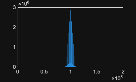
corrOut = xcorr(rxdata.',data);
Compute ToF2 at radio 1.
[val, ind] = max(abs(corrOut));
plot(abs(corrOut));
% Compute the peak location by compensating for the correlation delay
actualIndex = ind-length(rxdata)
actualIndex = 164
samplingFreq = radio1SampleRate;
sampleTime = 1/samplingFreq;

% Compute the correlation peak time from the peak location

% Compute the time at which the first sample was received.
receivedTimeStamp = datetime(metadata.TimestampInt, 'convertfrom', 'posixtime', 'Format', 'MM/dd/yy HH:mm:ss.SSSSSSSSS','TimeZone','Asia/Calcutta')+seconds(metadata.TimestampFrac);

% Compute the time at which the correlation peak occurred
radio1ReceivedPeak = receivedTimeStamp+seconds(sampleTime*actualIndex);

% Compute the delay from radio in reception after the trigger time if any
radioRxDelay = seconds(receivedTimeStamp-radio1RxTriggerTime);

% Estimate the time of flight as the difference in the time at which the
% peak occurred to the time at which the transmission was triggered from
% the other radio. Also take into consideration the reception delay of the
% radio
ToF2 = seconds(radio1ReceivedPeak-radio2TxTriggerTime)-radioRxDelay
ToF2 =
4.1000e-06
Compute Time of Flight
To compute the total time of flight, ToF, use:
The measured ToF includes the actual propagation time plus an unknown internal delay (offset) from each radio. To compute the exact distance, eliminate this offset as follows:
Estimate the internal offset
Place both radios at zero distance (antennas connected or very close).
Enable the referenceCalculation flag in both scripts and run them.
Record ToF₁ and ToF₂. These values represent the internal delays of the radios.
Compute the average of ToF₁ and ToF₂. This average value is the offset.
Compute distance for an unknown separation
Disable the referenceCalculation flag in both scripts.
Run the scripts to measure ToF₁ and ToF₂ for the actual setup.
Compute ToF as the average of ToF₁ and ToF₂.
Subtract the previously measured offset from this ToF.
Multiply the corrected ToF by the speed of light to obtain the distance.
Release the radio 1.
release(tx1);
release(rx1);
Calibrate Offset and Compute Distance:
The measured ToF includes the actual propagation time and an internal radio delay (offset). You first calibrate the offset at zero distance, then subtract it from later ToF measurements to compute the true distance. Enable referenceCalculation when you place the radios at zero distance; disable it for unknown distances.
if(referenceCalculation)
    save("referenceData1.mat","ToF2");
else
    save("TOAdata1.mat","ToF2");
end
When you disable referenceCalculation, load the saved reference ToFs and the current measurement ToFs, compute the offset, subtract it, and convert to meters.
if(~referenceCalculation)
    load("referenceData1.mat");
    load("referenceData2.mat");
    Offset = (ToF1+ToF2)/2;
    clear ToF1 ToF2
    load("TOAdata1.mat");
    load("TOAdata2.mat");
    ToF = (ToF1+ToF2)/2;
Distance = (ToF-Offset)*physconst('LightSpeed')
end
Distance =
22.4844
Distance is the unknown separation between the radios in meters, after removing the internal offset.
Tips to improve Accuracy of Distance Measurement:
Calculate the measurement resolution as the distance corresponding to one sample duration. For example, at a sample rate of 30e6, the sample time is 3.334e‑08 seconds. Multiply this by the speed of light to get about 10 meters. Expect the estimated distance to have a precision of approximately 10 meters.
Make sure both radios lock to GPS signals before running the example. GPS lock is essential for accurate time synchronization.
Check the correlation plot and confirm a clear peak during both reference and measurement runs. A sharp peak indicates correct signal reception and improves offset estimation. If the peak is unclear, the delay values may be incorrect. Repeat the example multiple times with proper peaks and average the results for best accuracy.