What Is a RoadRunner Pose Matrix?
The pose of an actor in a RoadRunner Scenario simulation refers to the position and orientation of the actor within the scene. When communicating with MATLAB® or Simulink®, an actor pose is specified as a four-by-four real pose matrix. This topic explains how to extract actor position and orientation from this matrix.
The pose matrix is a linear transformation matrix with a rotation component and a translation component. For example, this sample pose matrix is obtained from a scenario simulation log for a vehicle along with its rotation and translation components.
pose =
    0.1694    0.9855   -0.0000  -94.4264
   -0.9855    0.1694   -0.0000  -13.5663
   -0.0000    0.0000    1.0000    0.0000
         0         0         0    1.0000
rotation =
0.1694 0.9855 -0.0000
-0.9855 0.1694 -0.0000
-0.0000 0.0000 1.0000translation =
-94.4264
-13.5663
0.0000You may encounter a pose matrix in several locations:
Scenario simulation logs
In a MATLAB System object™ that defines an actor behavior
In a Simulink model that defines an actor behavior
Coordinate System in RoadRunner
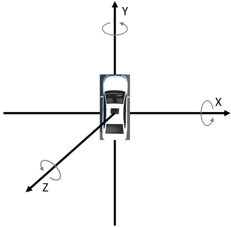
RoadRunner uses a three-dimensional right-direction coordinate system with X, Y, and Z components. In the default top-down view of a scene, the positive X direction is east (right), the positive Y direction is north (up), and the positive Z direction is out of the scene, toward the camera. Rotation around the X axis is also referred to as pitch. Rotation around the Y axis is also referred to as roll. Rotation around the Z axis is also referred to as yaw.
This figure shows the default position and orientation of a RoadRunner actor overlaid on the three coordinate axes. The direction of positive rotation is indicated by circular arrows.

The origin is the point referred to by the vector [0 0 0]. You can
change the origin point using the World Settings Tool (RoadRunner).
The pose matrix is a linear transformation from the default position and orientation to the current position and orientation of an actor. The default position and orientation of a RoadRunner actor is:
The center of the actor is at the origin in X and Y.
The wheels of the actor are touching the XY plane. The Z position of the center of the actor is adjusted accordingly.
The actor is facing the positive Y direction, or north.
Note
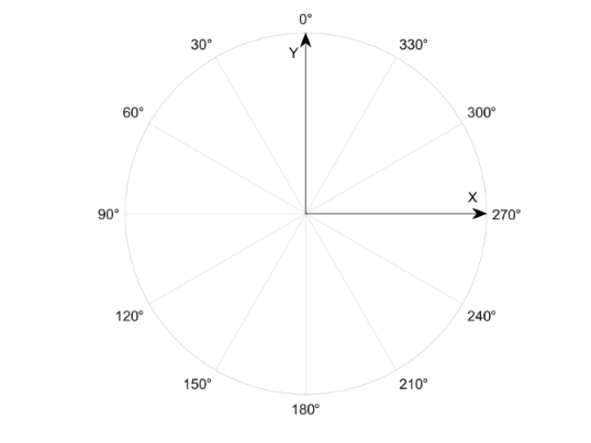
In RoadRunner, a rotation of zero corresponds to the positive Y
direction. To convert from RoadRunner conventions to systems in which zero rotation corresponds to the
positive X direction, add 90 degrees or pi/2
radians to yaw values.
This figure shows the yaw angle convention that RoadRunner uses.

Extract Rotation and Translation Components
The four-by-four pose matrix is a linear transformation matrix with a rotation component and a translation component.
Rotation Component
The upper three-by-three submatrix specifies rotation.
In autonomous systems applications, rotation is often specified in terms of Euler angles, which are rotations around the Y-axis (roll), X-axis (pitch), and Z-axis (yaw).
To convert a rotation matrix to Euler angles, follow these steps.
Extract the rotation submatrix.
rotation = pose(1:3, 1:3)
rotation = 0.1694 0.9855 -0.0000 -0.9855 0.1694 -0.0000 -0.0000 0.0000 1.0000Create a quaternion representation of this rotation matrix. For more information, see
quaternion.q = quaternion(rotation, "rotmat", "point")
q = quaternion 0.76465 + 4.1994e-09i - 3.5392e-09j - 0.64444kConvert the quaternion to Euler angles in radians.
eulerAnglesRad = euler(q, "ZYX", "point")
eulerAnglesRad = -1.4006 -0.0000 0.0000
Convert the quaternion to Euler angles in degrees.
eulerAnglesDeg = eulerd(q, "ZYX", "point")
eulerAnglesDeg = -80.2474 -0.0000 0.0000
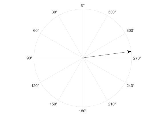
eulerAnglesRadandeulerAnglesDegcontain rotation angles around the axes in the specified order of Z (yaw), Y (roll), X (pitch). In this example, the actor has a yaw of -80.2474 degrees and zero roll and pitch. This figure shows the yaw of the actor.
For more information on these functions, see and
eulerandeulerd.
Alternatively, if you have a license for Navigation Toolbox™, Robotics System Toolbox™, or UAV Toolbox, you can use the rotm2eul (Navigation Toolbox) and eul2rotm (Navigation Toolbox) functions to convert rotation matrices to and from Euler
angles.
Extract the rotation submatrix.
rotation = pose(1:3, 1:3)
rotation = 0.1694 0.9855 -0.0000 -0.9855 0.1694 -0.0000 -0.0000 0.0000 1.0000Extract the Euler angles in radians from the rotation matrix.
eulerAnglesRad = rotm2eul(rotation, "ZYX")eulerAnglesRad = -1.4006 0.0000 0.0000
Extract the Euler angles in degrees from the rotation matrix.
eulerAnglesDeg = rad2deg(rotm2eul(rotation, "ZYX"))eulerAnglesDeg = -80.2474 0.0000 0.0000
Translation Component
The first three rows of the fourth column are the translation component of the pose matrix. This component is a 3D vector representing translation in the X, Y, and Z directions, relative to the origin of the RoadRunner scene. To extract the translation vector, use this code.
translation = pose(1:3, 4)
translation =
  -94.4264
  -13.5663
0.0000This actor is 94.4264 meters west of the origin and 13.5663 meters south of the origin, and the wheels of the actor are on the XY plane.
For more information about coordinate transformations and rotation matrices, see Coordinate Transformations in Robotics (Robotics System Toolbox) and Rotation Matrices (Phased Array System Toolbox). For a general introduction to coordinate systems used in Automated Driving Toolbox™, see Coordinate Systems in Automated Driving Toolbox.
See Also
Overview of Simulating RoadRunner Scenarios with MATLAB and Simulink | getAttribute