Triple-Axis Tilt Calculation Using LIS3DH FIFO Data Ready Interrupt
This example shows how to use the FIFO data ready interrupt of LIS3DH linear accelerometer connected to a STMicroelectronics® STM32 processor based board to sense the tilt of the sensor. This dection uses a downstream function-call subsystem that reads acceleration values from FIFO buffer sensor.
The sensor block placement is inside the downstream function-call subsystem. The output of the sensor block is sent to a MATLAB Function block where the data is averaged, and tilt is calculated.
For more information on tilt sensing using accelerometer values, see Using an Accelerometer for Inclination Sensing.
Prerequisites
Before working with this example, it is helpful to get familiar with the information in Getting Started with STMicroelectronics STM32 Processor Based Boards. This topic provides information about working with the STMicroelectronics CubeMX software for board I/O configuration.
Required Hardware
To run this example, you need this hardware:
Supported STMicroelectronics STM32F767ZI processor board
USB cable
Breadboard wires
Hardware Connection
Connect the INT1 pin of the LIS3DH sensor to pin PE11 on the STMicroelectronics STM32 processor based board.
Connect the SDA, SCL, 3.3V, and GND pin of the STMicroelectronics STM32 processor based board to the respective pins on the LIS3DH sensor.
Hardware Configuration in the Model
Open the model stnucleo_LIS3DH_tiltdetection_ec. In the Command Window, type:
open_system('stnucleo_LIS3DH_tiltdetection_ec.slx');

The model is preconfigured to work with STM32 F767ZI processor. If you are using a different STMicroelectronics STM32 processor based board, change the hardware board by performing the following steps:
1. Navigate to Modeling > Model Settings to open the Configuration Parameters dialog box.
2. Open the Hardware Implementation pane, and from the Hardware board list, select the STMicroelectronics STM32 processor based board that you are using.
3. Click Apply. Click OK to close the dialog box.
Configure the FIFO Data Ready Interrupt on LIS3DH for Interrupt Service Routine (ISR)
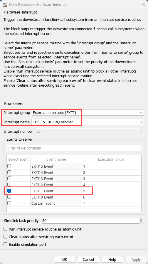
1. In the Simulink model, open the External Interrupt block, and ensure that the value of Pin number parameter is set to PE11, which is same as the STMicroelectronics STM32 processor based board pin that is connected to INT1 pin on LIS3DH sensor. If required, you can change the pin. For example, connect INT1 to another pin that supports External Interrupt on the STMicroelectronics STM32 processor based board.
The LIS3DH sensor block is placed in the downstream function call-sub system. The output of the block is connected to MATLAB function block. The FIFO data acquired by the MATLAB function is averaged, and tilt of each axis is calculated.
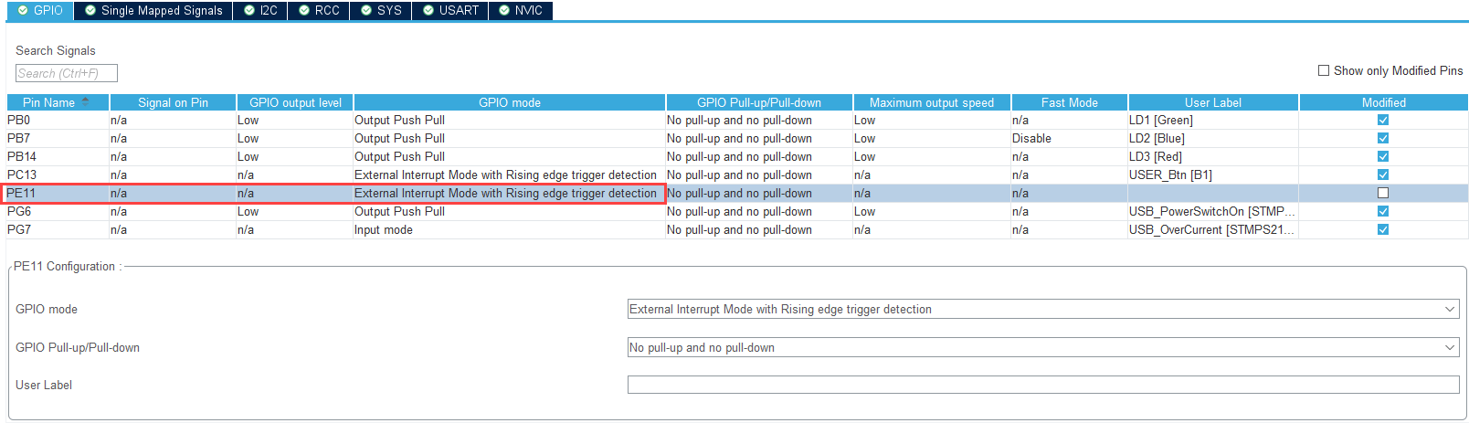
2. This example includes an STM32 CubeMX project file i2c_lis3dh_tripleAxisTilt.ioc that configures I/O connections for code generation. As shown in Getting Started with STMicroelectronics STM32 Processor Based Boards, you can browse to the project file from the Configuration Parameters dialog box. Or, you could use the STM32 CubeMX software to create a project file. Launch the STM32CubeMX project in the STM32CubeMX tool and apply configurations to enable to GPIO as shown in STM32 CubeMX.
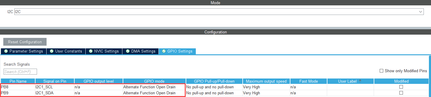
3. In AVR targets, for the I2C calls to work from within ISR, place sei(); inside the ISR. The sei() is added to the model using System Output block. The sei() is guarded to be included only for AVR targets and not the ARM® targets. Use this I2C configuration in STM32 CubeMX.
4. Ensure that the Generate data ready interrupt on INT1 pin parameter is selected, and also ensure that FIFO is enabled and Number of samples to read from FIFO (1-32) is provided. In this example, data update is expected at 100 Hz (the specified ODR) and Number of samples to read from FIFO is 10.

Initiate Monitor and Tune Action for the Model
During Monitor and Tune action, the model is deployed as a C code on the hardware. The code obtains real-time data from the hardware. The data acquisition and parameter tuning are done while the application is running on the hardware.
1. On the Hardware tab, in the Mode section, select Run on board (External Mode) and then click Monitor & Tune.

The lower-left corner of the model window displays status while Simulink prepares, downloads, and runs the Simulink model on the hardware. During simulation, the pin PE11 on STMicroelectronics STM32 processor based board generates an interrupt on every rising edge of the signal, which triggers the function-call subsystem.
2. Move the sensor and verify the changing values at each time step by double-clicking the Display blocks in the Display data area of the model.
Close Model
bdclose('stnucleo_LIS3DH_tiltdetection_ec');