Get Started with SystemVerilog DPI Component Generation
This example shows how to generate a SystemVerilog DPI component from a proportional-integral-derivative (PID) controller in a Simulink® model and how to export the component to an HDL simulator.
Requirements and Prerequisites
These products are required for this example.
One of these supported HDL simulators: Siemens® ModelSim™/QuestaSim™ or Cadence® Xcelium™
One of these supported C compilers: Microsoft® Visual C++ or GNU GCC
Set Up Model for Code Generation
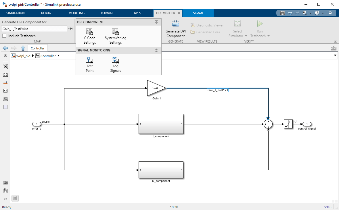
To set up the model with the correct target file, open the HDL Verifier app by clicking its app icon from the Apps tab. This action adds the HDL Verifier tab to the Simulink Toolstrip. Then, in the Mode section select DPI Component Generation to set the system target file of the model to "systemverilog_dpi_grt.tlc". If Embedded Coder® is installed, the target file is set to "systemverilog_dpi_ert.tlc" instead.
To generate a SystemVerilog testbench for the DPI component, in the Map section on the HDL Verifier tab, select Include Testbench.

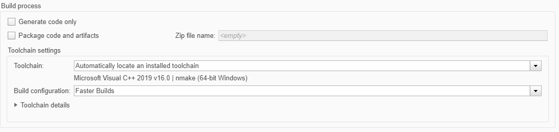
Open the configuration parameters for the model, by clicking C Code Settings in the Prepare section.
In the Toolchain settings section, select one of the Visual Studio® versions if you are using Windows® or one of the GCC toolchains if you are using Linux®.
Clear Generate code only.
Select Internal Signals for Test Point Logging (Optional)
To access internal signals of the DPI component in the SystemVerilog environment, use the DPI-C test point logging capability.
Double-click a signal you want to access to highlight the signal and to enter a signal name for it. To mark the signal as a test point, from the Prepare section of the Simulink Toolstrip, click Test Point. To also capture the test vector of the internal signal and playing the vector back in the generated testbench, click Log Signals in the gallery while the signal is highlighted.
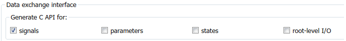
Enable C API options. In the Configuration Parameters dialog box, on the Code Generation > Interface tab, select signals.
Choose the interface of the SystemVerilog functions that you want to use to access the test points. Customize the generated DPI component by using option on the Code Generation > SystemVerilog DPI tab.
Under Test Point Access Functions, when you set Generate access function to test point to None, test points that are marked are ignored, and no access functions are generated. Changing the value to One function per test point enables you to access each test point independently. This figure shows the interface generated for this example.

Using the value One function for all test points enables you to access all of the test points with one function call.
Generate SystemVerilog DPI Component
In the
svdpi_pidSimulink model, select the Controller Subsystem block. In the Generate section on the toolstrip, click Generate DPI Component.Click Build in the dialog box that appears.
The SystemVerilog component is generated as
Controller_build/Controller_dpi.sv. When code generation is complete, examine the new component.
Run Generated Testbench
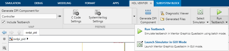
To select an HDL simulator, click Select Simulator in the Verify section of the toolstrip, and select an HDL simulator or add a simulator to the path.
To simulate the SystemVerilog testbench in batch mode, click Run Testbench. Alternatively, you can execute the simulation in GUI mode by clicking Run Testbench > Launch Simulator in GUI mode.
When the simulation finishes, this text prints in the console.
**************TEST COMPLETED (PASSED)**************