Main Content

4-Way 2-Position Directional Valve (IL)

4-way 2-position directional valve in an isothermal liquid network

Since R2021a

Libraries:
Simscape / Fluids / Isothermal Liquid / Valves & Orifices / Directional Control Valves

Description

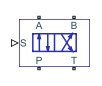
The 4-Way 2-Position Directional Valve (IL) block models a valve with four openings — such as the valves between an actuator, pump, and tank — in an isothermal liquid network. The valve operation is controlled by a single spool displaced according to the signal at port S. You can set the baseline configuration of your valve by specifying the orifices that are open when the spool moves in the positive direction and negative directions in the Positive spool position open connections and Negative spool position open connections parameters, respectively. You can set the valve opening model in the Orifice parameterization parameter as a linear relationship or function of user-provided data, which you can apply to one or all flow paths in the valve.

This block is a composite component that comprises of multiple instances of the Orifice (IL) block. Refer to the Orifice (IL) block for more details about the valve parameterizations and block calculations. In some configurations, this valve resembles a 3-way valve. To set additional flow paths when the spool is in the neutral position, see the 4-Way 3-Position Directional Valve (IL) block.

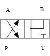
This image shows an example valve setup where the valve is connected to a tank, actuator, and pump and the Positive spool position open connections parameter is P-B and A-T:

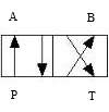
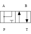
This image shows the valve when the Negative spool position open connections parameter is P-A and B-T:

In this configuration, when the signal at port S moves the spool to a negative position, the paths between ports P and A and between ports B and T are open to flow. The paths between ports P and B and ports A and T are closed to flow.

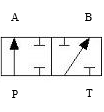
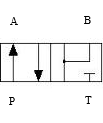
This image shows the valve when the Positive spool position open connections parameter is P-B and A-T:

In this configuration, when the signal at port S moves the spool to a positive position, the paths between ports P and B and between ports A and T are open to flow and the paths between ports P and A and between ports B and T are closed.

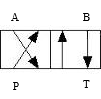
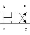
The schematic that represents this configuration is:

The left-hand side corresponds to the positive position and the right-hand side corresponds to the negative position. The valve transitions through positions in the neutral mid-section.

Spool Displacement and Valve Configuration

The spool stroke is the amount of spool travel an orifice takes to fully open from a closed position. You can use the Orifice parameterization and Area characteristics parameters to specify the flow path characteristics:

Orifice ParameterizationIdentical for All Flow PathsDifferent for Each Flow Path
Linear - Area vs. spool travelThe Spool travel between closed and open orifice parameter defines the spool strokeThe Spool travel between closed and open orifice parameter defines the spool stroke for each orifice
Tabulated data - Area vs. spool travelThe difference between the first and last element of the Spool travel vector parameter defines the spool strokeThe difference between the first and last element of the Spool travel vector parameter for each orifice
Tabulated data - Volumetric flow rate vs. spool travel and pressure dropThe difference between the first and last element of the Spool travel vector, ds parameter defines the spool strokeThe difference between the first and last element of the Spool travel vector, ds parameter defines the spool stroke for each orifice

The direction of the spool movement depends on the spool stroke, orifice orientation, and signal at port S. This table shows the spool travel for an orifice depending on the selections for the Positive spool position open connection and Negative spool position open connection parameters:

Spool Position When Orifice Is OpenSpool Travel, ΔS
Orifice always closed: orifice not selected for the Positive spool position open connection or Negative spool position open connection parametersN/A
Orifice always open: orifice selected for both the Positive spool position open connection and Negative spool position open connection parametersN/A
Negative: orifice selected for only Negative spool position open connection parameterSorifice_max + spool stroke – S
Positive: orifice selected for only Positive spool position open connection parameterSorifice_max – spool stroke + S

Where Sorifice_max is the spool position at the maximum orifice area defined for each orifice. The orifice area saturates at the leakage area when ΔS is negative and saturates at the maximum orifice area when the orifice is fully open. When the orifice is fully open, ΔS is equal to the spool stroke, so ΔS greater than the spool stroke does not further increase the orifice area.

This table shows the possible configurations of the 4-Way 2-Position Directional Valve (IL):

ConfigurationParameter Values

All four paths are closed during transition.

  • Positive spool position open connections: P-A and B-T

  • Negative spool position open connections: P-B and A-T

  • Spool position at maximum P-A orifice area > P-A spool stroke

  • Spool position at maximum P-B orifice area < –P-B spool stroke

  • Spool position at maximum A-T orifice area < –A-T spool stroke

  • Spool position at maximum B-T orifice area > B-T spool stroke

All four paths are open during transition.

  • Positive spool position open connections: P-A and B-T

  • Negative spool position open connections: P-B and A-T

  • Spool position at maximum P-A orifice area < P-A spool stroke

  • Spool position at maximum P-B orifice area > –P-B spool stroke

  • Spool position at maximum A-T orifice area > –A-T spool stroke

  • Spool position at maximum B-T orifice area < B-T spool stroke

A-T and B-T are closed during transition.

  • Positive spool position open connections: P-A and B-T

  • Negative spool position open connections: P-B and A-T

  • Spool position at maximum P-A orifice area < P-A spool stroke

  • Spool position at maximum P-B orifice area > –P-B spool stroke

  • Spool position at maximum A-T orifice area < –A-T spool stroke

  • Spool position at maximum B-T orifice area > B-T spool stroke

P-A and P-B are closed during transition.

  • Positive spool position open connections: P-A only

  • Negative spool position open connections: P-B only

  • Spool position at maximum P-A orifice area > P-A spool stroke

  • Spool position at maximum P-B orifice area < –P-B spool stroke

P-B and B-T are closed during transition.

  • Positive spool position open connections: P-B and A-T

  • Negative spool position open connections: P-A and B-T

  • Spool position at maximum P-A orifice area < P-A spool stroke

  • Spool position at maximum P-B orifice area > P-B spool stroke

  • Spool position at maximum A-T orifice area > A-T spool stroke

  • Spool position at maximum B-T orifice area < –B-T spool stroke

P-A and A-T are closed during transition.

  • Positive spool position open connections: P-B and A-T

  • Negative spool position open connections: P-A and B-T

  • Spool position at maximum P-A orifice area < –P-A spool stroke

  • Spool position at maximum P-B orifice area < P-B spool stroke

  • Spool position at maximum A-T orifice area > A-T spool stroke

  • Spool position at maximum B-T orifice area > –B-T spool stroke

P-A, P-B, and B-T are open during transition.

  • Positive spool position open connections: P-A and P-B

  • Negative spool position open connections: P-A and B-T

  • Spool position at maximum P-A orifice area < P-A spool stroke

  • Spool position at maximum P-B orifice area < P-B spool stroke

  • Spool position at maximum A-T orifice area = any value

  • Spool position at maximum B-T orifice area > –B-T spool stroke

P-A, A-T, and B-T are open during transition.

  • Positive spool position open connections: P-B and A-T

  • Negative spool position open connections: P-A and P-B

  • Spool position at maximum P-A orifice area > –P-A spool stroke

  • Spool position at maximum A-T orifice area < A-T spool stroke

  • Spool position at maximum B-T orifice area = any value

P-A and P-B are closed during transition. A-T is always closed.

  • Positive spool position open connections: P-A and P-B

  • Negative spool position open connections: P-A and B-T

  • Spool position at maximum P-B orifice area > P-B spool stroke

  • Spool position at maximum B-T orifice area < –B-T spool stroke

All paths are closed during transition.

  • Positive spool position open connections: P-B and A-T

  • Negative spool position open connections: P-A and P-B

  • Spool position at maximum P-A orifice area < –P-A spool stroke

  • Spool position at maximum P-B orifice area > P-B spool stroke

  • Spool position at maximum A-T orifice area > A-T spool stroke

A-T is open during transition. P-A is closed during transition.

  • Positive spool position open connections: P-A and P-B

  • Negative spool position open connections: P-A and B-T

  • Spool position at maximum P-A orifice area > P-A spool stroke

  • Spool position at maximum P-B orifice area > P-B spool stroke

  • Spool position at maximum A-T orifice area = any value

  • Spool position at maximum B-T orifice area > –B-T spool stroke

B-T is open during transition. P-B is closed during transition.

  • Positive spool position open connections: P-B and A-T

  • Negative spool position open connections: P-A and P-B

  • Spool position at maximum P-A orifice area < –P-A spool stroke

  • Spool position at maximum P-B orifice area > P-B spool stroke

  • Spool position at maximum A-T orifice area < A-T spool stroke

  • Spool position at maximum B-T orifice area = any value

P-A is closed during transition.

  • Positive spool position open connections: P-A and B-T

  • Negative spool position open connections: P-A and P-B

  • Spool position at maximum P-A orifice area > P-A spool stroke

  • Spool position at maximum P-B orifice area < –P-B spool stroke

  • Spool position at maximum B-T orifice area > B-T spool stroke

P-B is closed during transition.

  • Positive spool position open connections: P-A and P-B

  • Negative spool position open connections: P-B and A-T

  • Spool position at maximum P-A orifice area > P-A spool stroke

  • Spool position at maximum P-B orifice area > P-B spool stroke

  • Spool position at maximum A-T orifice area > –A-T spool stroke

Valve Orifice Parameterizations

The Orifice parameterization parameter specifies the model for the open area or volumetric flow rate through one or all of the valve orifices. If you set Area characteristics to Identical for all flow paths, the block applies the same data for all flow paths. When you select Different for all flow paths, the block uses individual parameterizations for each flow path.

When Orifice parameterization is Linear - area vs. spool travel, the opening area is a linear function of the spool position received as a signal at port S

Aorifice=(AmaxAleak)ΔSmaxΔS+Aleak,

where:

  • ΔS is the spool travel.

    Aorifice saturates at Aleak when ΔS is negative and saturates at Amax when the orifice is fully open. When the orifice is fully open, ΔS is equal to the spool stroke, so a value of ΔS that is greater than the spool stroke does not increase the orifice area.

  • ΔSmax is the value of the Spool travel between closed and open orifice parameter.

  • Amax is the value of the Maximum orifice area parameter.

  • Aleak is the value of the Leakage area parameter.

    When the valve is in a near-open or near-closed position in the linear parameterization, you can maintain numerical robustness in your simulation by adjusting the Smoothing factor parameter. If the Smoothing factor parameter is nonzero, the block smoothly saturates the opening area between Aleak and Amax. For more information, see Numerical Smoothing.

When Orifice parameterization is Tabulated data - Area vs. spool travel, you can provide spool travel vectors for your system or for individual flow paths between ports P, A, B, and T. The block uses this data to calculate the relationship between the orifice area and spool displacement. The block uses interpolation to determine the opening area between the data points. Aleak and Amax are the first and last parameters of the opening area vector, respectively.

When Orifice parameterization is Tabulated data - Volumetric flow rate vs. spool travel and pressure drop, you can provide spool travel and pressure drop vectors and a dependent, 2-D volumetric flow rate array. The block uses interpolation to determine the flow rate between the data points. The mass flow rate is the product of the volumetric flow rate and the local density.

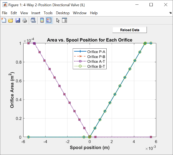
Visualize Orifice Openings

To visualize the spool offsets and maximum displacement, right-click the block and select Fluids > Plot Valve Characteristics. The plot shows the orifices specified by the parameters in Valve Configuration section. The axes are either:

  • Orifice Area verses Spool Position

  • Volumetric Flow Rate verses Spool Position, queried at a specific pressure differential

When you set the parameters in the Valve Configuration tab to the same orifice, the orifice opening is a constant.

Click Reload Data to update the data in the figure.

This image shows the default configuration for the block:

  • Positive spool position open connections is P-A and B-T.

  • Negative spool position open connections is P-B and A-T.

All other spool positions are at the default values.

Example Spool Position Visualization

Faults

To model a fault, in the Faults section, click the Add fault hyperlink next to the fault that you want to model. In the Add Fault window, specify the fault properties. For more information about fault modeling, see Introduction to Simscape Faults.

The Spool position when faulted parameter has three fault options:

  • Positive — The spool position freezes in the positive position, opening the flow paths specified by the Positive spool position open connections parameter to their maximum value. The flow paths specified by the Negative spool position open connections parameter are closed.

  • Negative — The spool position freezes in the negative position, opening the flow paths specified by the Negative spool position open connections parameter to their maximum value. The flow paths specified by the Positive spool position open connections parameter are closed.

  • Maintain last value — The valve freezes at the spool position when the trigger occurs.

Due to numerical smoothing at the extremes of the valve area, in the linear parameterization, the minimum area that he block uses is larger than the Leakage area, and the maximum is smaller than the Maximum orifice area, in proportion to the Smoothing factor value. For more information, see Numerical Smoothing.

After the fault triggers, the valve remains at the faulted area for the rest of the simulation.

Predefined Parameterization

You can populate the block with pre-parameterized manufacturing data, which allows you to model a specific supplier component.

To load a predefined parameterization:

  1. In the block dialog box, next to Selected part, click the "<click to select>" hyperlink next to Selected part in the block dialogue box settings.

  2. The Block Parameterization Manager window opens. Select a part from the menu and click Apply all. You can narrow the choices using the Manufacturer drop down menu.

  3. You can close the Block Parameterization Manager menu. The block now has the parameterization that you specified.

  4. You can compare current parameter settings with a specific supplier component in the Block Parameterization Manager window by selecting a part and viewing the data in the Compare selected part with block section.

Note

Predefined block parameterizations use available data sources to supply parameter values. The block substitutes engineering judgement and simplifying assumptions for missing data. As a result, expect some deviation between simulated and actual physical behavior. To ensure accuracy, validate the simulated behavior against experimental data and refine your component models as necessary.

To learn more, see List of Pre-Parameterized Components.

Ports

Conserving

expand all

Liquid entry or exit port to the valve.

Liquid entry or exit port to the valve.

Liquid entry or exit port to the valve.

Liquid entry or exit port to the valve.

Input

expand all

Physical signal associated with the spool displacement, in m.

Parameters

expand all

Valve Configuration

Flow paths open when the spool is in a positive position. This parameter sets the valve configuration and defines the direction of spool movement according to the signal received at port S.

Flow paths open when the spool moves in the negative direction. This parameter sets the valve configuration and defines the direction of spool movement according to the signal received at port S.

Model Parameterization

Whether to apply uniform or individual flow equations for the valve orifice area. When you set this parameter to Identical for all flow paths, the block uses the same orifice and spool geometries, flow rates, pressure, and area vectors for all valve orifices. When you set this parameter to Different for each flow path, you can specify these parameters individually for each orifice. For both settings, orifices A, B, P, and T have the same cross-sectional areas, discharge coefficients, and Reynolds numbers when you set Orifice parameterization to Linear - Area vs. spool travel or Tabulated data - Area vs. spool travel.

Method of calculating the valve opening area. If you set this parameter to one of the tabulated data parameterizations, you can provide your own valve area and spool travel data for nonlinear valve opening profiles, or provide data in terms of volumetric flow rate, spool travel, and pressure drop over the flow path.

Maximum distance of spool travel.

Dependencies

To enable this parameter, set Area characteristics to Identical for all flow paths and Orifice parameterization to Linear - Area vs. spool travel.

Largest open area of each orifice during the operation of the valve.

Dependencies

To enable this parameter, set Area characteristics to Identical for all flow paths and Orifice parameterization to Linear - Area vs. spool travel.

Open area when an orifice is fully closed. The block maintains any area smaller than this value at the specified leakage area. This parameter contributes to numerical stability by maintaining continuity in the flow.

Dependencies

To enable this parameter, set Orifice parameterization to Linear - Area vs. spool travel.

Vector of spool travel distances when parameterizing the orifice according to tabulated valve area data. The vector elements must correspond one-to-one with the elements in the Orifice area vector parameter. List the values in ascending order. The first element must be 0. The block uses linear interpolation between table data points.

Dependencies

To enable this parameter, set Area characteristics to Identical for all flow paths and Orifice parameterization to Tabulated data - Area vs. spool travel.

Vector of opening areas when parameterizing the orifice according to tabulated valve area data. The vector elements must correspond one-to-one with the elements in the Spool travel vector parameter. List the values in ascending order. The elements must be greater than 0.

Dependencies

To enable this parameter, set Area characteristics to Identical for all flow paths and Orifice parameterization to Tabulated data - Area vs. spool travel.

Vector of spool travel distances when parameterizing the orifice according to tabulated volumetric flow rate data. The spool travel vector forms an independent axis with the Pressure drop vector, dp parameter for the 2-D dependent Volumetric flow rate table, q(ds,dp) parameter. List the values in ascending order. The first element must be 0. The block uses linear interpolation between table data points.

Dependencies

To enable this parameter, set Area characteristics to Identical for all flow paths and Orifice parameterization to Tabulated data - Volumetric flow rate vs. spool travel and pressure drop.

Vector of pressure drop values when parameterizing the orifice according to tabulated flow rate data. The pressure drop vector forms an independent axis with the Spool travel vector, ds parameter for the 2-D dependent Volumetric flow rate table, q(ds,dp) parameter. List the values in ascending order. The values must be greater than 0. The block uses linear interpolation between table data points.

Dependencies

To enable this parameter, set Area characteristics to Identical for all flow paths and Orifice parameterization to Tabulated data - Volumetric flow rate vs. spool travel and pressure drop.

M-by-N matrix of volumetric flow rates based on independent values of pressure drop and spool travel distance. M and N are the sizes of the correlated vectors:

  • M is the number of vector elements in the Pressure drop vector, dp parameter.

  • N is the number of vector elements in the Spool travel vector, ds parameter.

Dependencies

To enable this parameter, set Area characteristics to Identical for all flow paths and Orifice parameterization to Tabulated data - Volumetric flow rate vs. spool travel and pressure drop.

Orifice area when the positive and negative spool positions include the same orifice.

Dependencies

To enable this parameter, set Area characteristics to Identical for all flow paths and Orifice parameterization to either:

  • Linear - area vs. spool travel

  • Tabulated data - Area vs. spool travel

Select the same orifice for both of the parameters in the Valve Configuration section:

  • Positive spool position open connections

  • Negative spool position open connections

Vector of pressure differential values over the valve when the positive and negative spool positions include the same orifice. The vector elements correspond one-to-one with the elements in the Constant orifice volumetric flow rate vector parameter. List the values in ascending order. The block uses linear interpolation between the data points.

Dependencies

To enable this parameter, set Area characteristics to Identical for all flow paths and Orifice parameterization to Tabulated data - Volumetric flow rate vs. spool travel and pressure drop.

Select the same orifice for both of the parameters in the Valve Configuration section:

  • Positive spool position open connections

  • Negative spool position open connections

Vector of volumetric flow rate values for a constant orifice when the positive and negative spool positions include the same orifice. The vector elements correspond one-to-one with the elements in the Constant orifice pressure drop vector parameter. List the values in ascending order. The block uses linear interpolation between the data points.

Dependencies

To enable this parameter, set Area characteristics to Identical for all flow paths and Orifice parameterization to Tabulated data - Volumetric flow rate vs. spool travel and pressure drop.

Select the same orifice for both of the parameters in the Valve Configuration section:

  • Positive spool position open connections

  • Negative spool position open connections

Maximum cross-sectional areas at the entry and exit ports P, T, A, and B, which the block uses in the pressure-flow rate equation that determines the mass flow rate through the valve.

Dependencies

To enable this parameter, set Area characteristics to Identical for all flow paths and Orifice parameterization to either:

  • Linear - area vs. spool travel

  • Tabulated data - Area vs. spool travel

Correction factor that accounts for discharge losses in theoretical flows.

Dependencies

To enable this parameter, set Orifice parameterization to either:

  • Linear - Area vs. spool travel

  • Tabulated data - Area vs. spool travel

Upper Reynolds number limit for laminar flow through the orifice.

Dependencies

To enable this parameter, set Orifice parameterization to:

  • Linear - area vs. spool travel

  • Tabulated data - Area vs. spool travel

Continuous smoothing factor that introduces a layer of gradual change based to the flow response when the valve is in near-open and near-closed positions. To increase the stability of your simulation in these regimes, set this parameter to a nonzero value less than one.

Dependencies

To enable this parameter, set Orifice parametrization to Linear - area vs. spool travel.

Whether to account for pressure increase when fluid flows from a region of smaller cross-sectional area to a region of larger cross-sectional area.

Dependencies

To enable this parameter, set Orifice parameterization to:

  • Linear - area vs. spool travel

  • Tabulated data - Area vs. spool travel

P-A Orifice

Spool offset from the neutral position for a fully open P-A orifice.

Dependencies

To enable this parameter, set one of these parameters.

Set Positive spool position open connections to:

  • P-A and B-T

  • P-A and P-B

  • P-A only

  • P-A, P-B, A-T, and B-T

Set Negative spool position open connections to:

  • P-A and B-T

  • P-A and P-B

  • P-A only

  • P-A, P-B, A-T, and B-T

Note:

This parameter is enabled only when the P-A orifice settings do not appear in both the Positive spool position open connections and Negative spool position open connections parameters.

Maximum distance of spool travel. This value provides an upper limit to calculations so that simulations do not return unphysical values.

Dependencies

To enable this parameter, set:

  1. Area characteristics to Different for each flow path.

  2. Orifice parameterization to Linear - Area vs. spool travel.

  3. One of the following parameters:

    Positive spool position open connections to:

    • P-A and B-T

    • P-A and P-B

    • P-A only

    • P-A, P-B, A-T, and B-T

    Negative spool position open connections to:

    • P-A and B-T

    • P-A and P-B

    • P-A only

    • P-A, P-B, A-T, and B-T

Largest open area of the P-A orifice during the operation of the valve.

Dependencies

To enable this parameter, set:

  1. Area characteristics to Different for each flow path.

  2. Orifice parameterization to Linear - Area vs. spool travel.

  3. One of the following parameters:

    Positive spool position open connections to:

    • P-A and B-T

    • P-A and P-B

    • P-A only

    • P-A, P-B, A-T, and B-T

    Negative spool position open connections to:

    • P-A and B-T

    • P-A and P-B

    • P-A only

    • P-A, P-B, A-T, and B-T

Vector of spool travel distances for the tabular parameterization of the valve area. The vector elements must correspond one-to-one with the elements in the P-A orifice area vector parameter. List the values in ascending order. The first element must be 0. The block uses linear interpolation between the data points.

Dependencies

To enable this parameter, set:

  1. Area characteristics to Different for each flow path.

  2. Orifice parameterization to Tabulated data - Area vs. spool travel.

  3. One of the following parameters:

    Positive spool position open connections to:

    • P-A and B-T

    • P-A and P-B

    • P-A only

    • P-A, P-B, A-T, and B-T

    Negative spool position open connections to:

    • P-A and B-T

    • P-A and P-B

    • P-A only

    • P-A, P-B, A-T, and B-T

Vector of opening areas for the tabular parameterization of the valve area. The vector elements must correspond one-to-one with the elements in the P-A spool travel vector parameter. The elements are listed in ascending order. The elements must be greater than 0.

Dependencies

To enable this parameter, set:

  1. Area characteristics to Different for each flow path.

  2. Orifice parameterization to Tabulated data - Area vs. spool travel.

  3. One of the following parameters:

    Positive spool position open connections to:

    • P-A and B-T

    • P-A and P-B

    • P-A only

    • P-A, P-B, A-T, and B-T

    Negative spool position open connections to:

    • P-A and B-T

    • P-A and P-B

    • P-A only

    • P-A, P-B, A-T, and B-T

Vector of spool travel distances for the tabular parameterization of the volumetric flow rates. The spool travel vector forms an independent axis with the P-A orifice pressure drop vector, dp parameter for the 2-D dependent P-A orifice volumetric flow rate table, q(ds,dp) parameter. List the values in ascending order. The first element must be 0. The block uses linear interpolation between the data points.

Dependencies

To enable this parameter, set:

  1. Area characteristics to Different for each flow path.

  2. Orifice parameterization to Tabulated data - Volumetric flow rate vs. spool travel and pressure drop.

  3. One of the following parameters:

    Positive spool position open connections to:

    • P-A and B-T

    • P-A and P-B

    • P-A only

    • P-A, P-B, A-T, and B-T

    Negative spool position open connections to:

    • P-A and B-T

    • P-A and P-B

    • P-A only

    • P-A, P-B, A-T, and B-T

Vector of pressure drop values for the tabular parametrization of the volumetric flow rates. The pressure drop vector forms an independent axis with the P-A orifice spool travel vector, ds parameter for the 2-D dependent P-A orifice volumetric flow rate table, q(ds,dp) parameter. List the values in ascending order. The elements must be greater than 0. The block uses linear interpolation between the data points.

Dependencies

To enable this parameter, set:

  1. Area characteristics to Different for each flow path.

  2. Orifice parameterization to Tabulated data - Volumetric flow rate vs. spool travel and pressure drop.

  3. One of the following parameters:

    Positive spool position open connections to:

    • P-A and B-T

    • P-A and P-B

    • P-A only

    • P-A, P-B, A-T, and B-T

    Negative spool position open connections to:

    • P-A and B-T

    • P-A and P-B

    • P-A only

    • P-A, P-B, A-T, and B-T

M-by-N matrix of volumetric flow rates based on independent values of pressure drop and spool travel distance. M and N are the sizes of the correlated vectors:

  • M is the number of vector elements in the P-A orifice pressure drop vector, dp parameter.

  • N is the number of vector elements in the P-A orifice spool travel vector, ds parameter.

Dependencies

To enable this parameter, set:

  1. Area characteristics to Different for each flow path.

  2. Orifice parameterization to Tabulated data - Volumetric flow rate vs. spool travel and pressure drop.

  3. One of the following parameters:

    Positive spool position open connections to:

    • P-A and B-T

    • P-A and P-B

    • P-A only

    • P-A, P-B, A-T, and B-T

    Negative spool position open connections to:

    • P-A and B-T

    • P-A and P-B

    • P-A only

    • P-A, P-B, A-T, and B-T

Orifice area when the positive and negative spool positions include the same orifice.

Dependencies

To enable this parameter, set:

  1. Area characteristics to Different for each flow path.

  2. Orifice parameterization to either:

    • Linear - area vs. spool travel

    • Tabulated data - Area vs. spool travel

  3. One of the following settings in each parameter:

    Positive spool position open connections to:

    • P-A and B-T

    • P-A and P-B

    • P-A only

    • P-A, P-B, A-T, and B-T

    Negative spool position open connections to:

    • P-A and B-T

    • P-A and P-B

    • P-A only

    • P-A, P-B, A-T, and B-T

Note:

This parameter is enabled only when the P-A orifice settings appear in both the Positive spool position open connections and Negative spool position open connections parameters.

Vector of pressure differential values over the valve when the positive and negative spool positions include the same orifice. The vector elements correspond one-to-one with the elements in the P-A Constant orifice volumetric flow rate vector parameter. List the values in ascending order. The block uses linear interpolation between the data points.

Dependencies

To enable this parameter, set:

  1. Area characteristics to Different for each flow path.

  2. Orifice parameterization to Tabulated data - Volumetric flow rate vs. spool travel and pressure drop.

  3. One of the following settings in each parameter:

    Positive spool position open connections to:

    • P-A and B-T

    • P-A and P-B

    • P-A only

    • P-A, P-B, A-T, and B-T

    Negative spool position open connections to:

    • P-A and B-T

    • P-A and P-B

    • P-A only

    • P-A, P-B, A-T, and B-T

Note:

This parameter is enabled only when the P-A orifice settings appear in both the Positive spool position open connections and Negative spool position open connections parameters.

Vector of pressure differential values over the valve when the positive and negative spool positions include the same orifice. The vector elements correspond one-to-one with the elements in the P-A Constant orifice pressure drop vector parameter. List the values in ascending order. The block uses linear interpolation between the data points.

Dependencies

To enable this parameter, set:

  1. Area characteristics to Different for each flow path.

  2. Orifice parameterization to Tabulated data - Volumetric flow rate vs. spool travel and pressure drop.

  3. One of the following settings in each parameter:

    Positive spool position open connections to:

    • P-A and B-T

    • P-A and P-B

    • P-A only

    • P-A, P-B, A-T, and B-T

    Negative spool position open connections to:

    • P-A and B-T

    • P-A and P-B

    • P-A only

    • P-A, P-B, A-T, and B-T

Note:

This parameter is enabled only when the P-A orifice settings appear in both the Positive spool position open connections and Negative spool position open connections parameters.

P-B Orifice

Spool offset from the neutral position for a fully open P-B orifice.

Dependencies

To enable this parameter, set one of the following parameters:

Positive spool position open connections to:

  • P-B and A-T

  • P-A and P-B

  • P-B only

  • P-A, P-B, A-T, and B-T

Negative spool position open connections to:

  • P-B and A-T

  • P-A and P-B

  • P-B only

  • P-A, P-B, A-T, and B-T

Note:

This parameter is enabled only when the P-B orifice settings do not appear in both the Positive spool position open connections and Negative spool position open connections parameters.

Maximum distance of spool travel. This value provides an upper limit to calculations so that simulations do not return unphysical values.

Dependencies

To enable this parameter, set:

  1. Area characteristics to Different for each flow path.

  2. Orifice parameterization to Linear - Area vs. spool travel.

  3. One of the following parameters:

    Positive spool position open connections to:

    • P-B and A-T

    • P-A and P-B

    • P-B only

    • P-A, P-B, A-T, and B-T

    or set Negative spool position open connections to:

    • P-B and A-T

    • P-A and P-B

    • P-B only

    • P-A, P-B, A-T, and B-T

Largest open area of the P-B orifice during the operation of the valve.

Dependencies

To enable this parameter, set:

  1. Area characteristics to Different for each flow path.

  2. Orifice parameterization to Linear - Area vs. spool travel.

  3. One of the following parameters:

    Positive spool position open connections to:

    • P-B and A-T

    • P-A and P-B

    • P-B only

    • P-A, P-B, A-T, and B-T

    Negative spool position open connections to:

    • P-B and A-T

    • P-A and P-B

    • P-B only

    • P-A, P-B, A-T, and B-T

Vector of spool travel distances for the tabular parameterization of the valve area. The vector elements must correspond one-to-one with the elements in the P-B orifice area vector parameter. List the values in ascending order. The first element must be 0. The block uses linear interpolation between the data points.

Dependencies

To enable this parameter, set:

  1. Area characteristics to Different for each flow path.

  2. Orifice parameterization to Tabulated data - Area vs. spool travel.

  3. One of the following parameters:

    Positive spool position open connections to:

    • P-B and A-T

    • P-A and P-B

    • P-B only

    • P-A, P-B, A-T, and B-T

    Negative spool position open connections to:

    • P-B and A-T

    • P-A and P-B

    • P-B only

    • P-A, P-B, A-T, and B-T

Vector of opening areas for the tabular parameterization of the valve area. The vector elements must correspond one-to-one with the elements in the P-B spool travel vector parameter. List the elements in ascending order. The elements must be greater than 0.

Dependencies

To enable this parameter, set:

  1. Area characteristics to Different for each flow path.

  2. Orifice parameterization to Tabulated data - Area vs. spool travel.

  3. One of the following parameters:

    Positive spool position open connections to:

    • P-B and A-T

    • P-A and P-B

    • P-B only

    • P-A, P-B, A-T, and B-T

    Negative spool position open connections to:

    • P-B and A-T

    • P-A and P-B

    • P-B only

    • P-A, P-B, A-T, and B-T

Vector of spool travel distances for the tabular parameterization of the volumetric flow rates. The spool travel vector forms an independent axis with the P-B orifice pressure drop vector, dp parameter for the 2-D dependent P-B orifice volumetric flow rate table, q(ds,dp) parameter. List the values in ascending order. The first element must be 0. The block uses linear interpolation between the data points.

Dependencies

To enable this parameter, set:

  1. Area characteristics to Different for each flow path.

  2. Orifice parameterization to Tabulated data - Volumetric flow rate vs. spool travel and pressure drop.

  3. One of the following parameters:

    Positive spool position open connections to:

    • P-B and A-T

    • P-A and P-B

    • P-B only

    • P-A, P-B, A-T, and B-T

    Negative spool position open connections to:

    • P-B and A-T

    • P-A and P-B

    • P-B only

    • P-A, P-B, A-T, and B-T

Vector of pressure drop values for tabular parametrization of the volumetric flow rates. The pressure drop vector forms an independent axis with the P-B orifice spool travel vector, ds parameter for the 2-D dependent P-B orifice volumetric flow rate table, q(ds,dp) parameter. List the values in ascending order. The elements must be greater than 0. The block uses linear interpolation between the data points.

Dependencies

To enable this parameter, set:

  1. Area characteristics to Different for each flow path.

  2. Orifice parameterization to Tabulated data - Volumetric flow rate vs. spool travel and pressure drop.

  3. One of the following parameters:

    Positive spool position open connections to:

    • P-B and A-T

    • P-A and P-B

    • P-B only

    • P-A, P-B, A-T, and B-T

    Negative spool position open connections to:

    • P-B and A-T

    • P-A and P-B

    • P-B only

    • P-A, P-B, A-T, and B-T

M-by-N matrix of volumetric flow rates based on independent values of pressure drop and spool travel distance. M and N are the sizes of the correlated vectors:

  • M is the number of vector elements in the P-B orifice pressure drop vector, dp parameter.

  • N is the number of vector elements in the P-B orifice spool travel vector, ds parameter.

Dependencies

To enable this parameter, set:

  1. Area characteristics to Different for each flow path.

  2. Orifice parameterization to Tabulated data - Volumetric flow rate vs. spool travel and pressure drop.

  3. One of the following parameters:

    Positive spool position open connections to:

    • P-B and A-T

    • P-A and P-B

    • P-B only

    • P-A, P-B, A-T, and B-T

    Negative spool position open connections to:

    • P-B and A-T

    • P-A and P-B

    • P-B only

    • P-A, P-B, A-T, and B-T

Orifice area when the positive and negative spool positions include the same orifice.

Dependencies

To enable this parameter, set:

  1. Area characteristics to Different for each flow path.

  2. Orifice parameterization to either:

    • Linear - area vs. spool travel

    • Tabulated data - Area vs. spool travel

  3. One of the following settings in each parameter:

    Positive spool position open connections to:

    • P-B and A-T

    • P-A and P-B

    • P-B only

    • P-A, P-B, A-T, and B-T

    Negative spool position open connections to:

    • P-B and A-T

    • P-A and P-B

    • P-B only

    • P-A, P-B, A-T, and B-T

Note:

This parameter is enabled only when the P-B orifice settings appear in both the Positive spool position open connections and Negative spool position open connections parameters.

Vector of pressure differential values over the valve when the positive and negative spool positions include the same orifice. The vector elements correspond one-to-one with the elements in the P-B Constant orifice volumetric flow rate vector parameter. List the values in ascending order. The block uses linear interpolation between the data points.

Dependencies

To enable this parameter, set:

  1. Area characteristics to Different for each flow path.

  2. Orifice parameterization to Tabulated data - Volumetric flow rate vs. spool travel and pressure drop.

  3. One of the following settings in each parameter:

    Positive spool position open connections to:

    • P-B and A-T

    • P-A and P-B

    • P-B only

    • P-A, P-B, A-T, and B-T

    Negative spool position open connections to:

    • P-B and A-T

    • P-A and P-B

    • P-B only

    • P-A, P-B, A-T, and B-T

Note:

This parameter is enabled only when the P-B orifice settings appear in both the Positive spool position open connections and Negative spool position open connections parameters.

Vector of volumetric flow rate values over the valve when the positive and negative spool positions include the same orifice. The vector elements correspond one-to-one with the elements in the P-B Constant orifice pressure drop vector parameter. List the values in ascending order. The block uses linear interpolation between the data points.

Dependencies

To enable this parameter, set:

  1. Area characteristics to Different for each flow path.

  2. Orifice parameterization to Tabulated data - Volumetric flow rate vs. spool travel and pressure drop.

  3. One of the following settings in each parameter:

    Positive spool position open connections to:

    • P-B and A-T

    • P-A and P-B

    • P-B only

    • P-A, P-B, A-T, and B-T

    Negative spool position open connections to:

    • P-B and A-T

    • P-A and P-B

    • P-B only

    • P-A, P-B, A-T, and B-T

Note:

This parameter is enabled only when the P-B orifice settings appear in both the Positive spool position open connections and Negative spool position open connections parameters.

A-T Orifice

Spool offset from the neutral position for a fully open A-T orifice.

Dependencies

To enable this parameter, set one of the following parameters:

  • Positive spool position open connections to P-B and A-T or P-A, P-B, A-T, and B-T.

  • Negative spool position open connections to P-B and A-T or P-A, P-B, A-T, and B-T.

Note:

This parameter is enabled only when the A-T orifice settings do not appear in both the Positive spool position open connections and Negative spool position open connections parameters.

Maximum distance of spool travel. This value provides an upper limit to calculations so that simulations do not return unphysical values.

Dependencies

To enable this parameter, set:

  1. Area characteristics to Different for each flow path.

  2. Orifice parameterization to Linear - Area vs. spool travel.

  3. One of the following parameters:

    • Positive spool position open connections to P-B and A-T or P-A, P-B, A-T, and B-T.

    • Negative spool position open connections to P-B and A-T or P-A, P-B, A-T, and B-T.

Largest open area of the A-T orifice during the operation of the valve.

Dependencies

To enable this parameter, set:

  1. Area characteristics to Different for each flow path.

  2. Orifice parameterization to Linear - Area vs. spool travel.

  3. One of the following parameters:

    • Positive spool position open connections to P-B and A-T or P-A, P-B, A-T, and B-T.

    • Negative spool position open connections to P-B and A-T or P-A, P-B, A-T, and B-T.

Vector of spool travel distances for the tabular parameterization of the valve area. The vector elements must correspond one-to-one with the elements in the A-T orifice area vector parameter. List the values in ascending order. The first element must be 0. The block uses linear interpolation between the data points.

Dependencies

To enable this parameter, set:

  1. Area characteristics to Different for each flow path.

  2. Orifice parameterization to Tabulated data - Area vs. spool travel.

  3. One of the following parameters:

    • Positive spool position open connections to P-B and A-T or P-A, P-B, A-T, and B-T.

    • Negative spool position open connections to P-B and A-T or P-A, P-B, A-T, and B-T.

Vector of spool travel distances for the tabular parameterization of the volumetric flow rates. The spool travel vector forms an independent axis with the A-T orifice pressure drop vector, dp parameter for the 2-D dependent A-T orifice volumetric flow rate table, q(ds,dp) parameter. List the values in ascending order. The first element must be 0. The block uses linear interpolation between the data points.

Dependencies

To enable this parameter, set:

  1. Area characteristics to Different for each flow path.

  2. Orifice parameterization to Tabulated data - Volumetric flow rate vs. spool travel and pressure drop.

  3. One of the following parameters:

    • Positive spool position open connections to P-B and A-T or P-A, P-B, A-T, and B-T.

    • Negative spool position open connections to P-B and A-T or P-A, P-B, A-T, and B-T.

Vector of pressure drop values for tabular parametrization of the volumetric flow rates. The pressure drop vector forms an independent axis with the A-T orifice spool travel vector, ds parameter for the 2-D dependent A-T orifice volumetric flow rate table, q(ds,dp) parameter. List the values in ascending order. The elements must be greater than 0. The block uses linear interpolation between the data points.

Dependencies

To enable this parameter, set:

  1. Area characteristics to Different for each flow path.

  2. Orifice parameterization to Tabulated data - Volumetric flow rate vs. spool travel and pressure drop.

  3. One of the following parameters:

    • Positive spool position open connections to P-B and A-T or P-A, P-B, A-T, and B-T.

    • Negative spool position open connections to P-B and A-T or P-A, P-B, A-T, and B-T.

M-by-N matrix of volumetric flow rates based on independent values of pressure drop and spool travel distance. M and N are the sizes of the correlated vectors:

  • M is the number of vector elements in the A-T orifice pressure drop vector, dp parameter.

  • N is the number of vector elements in the A-T orifice spool travel vector, ds parameter.

Dependencies

To enable this parameter, set:

  1. Area characteristics to Different for each flow path.

  2. Orifice parameterization to Tabulated data - Volumetric flow rate vs. spool travel and pressure drop.

  3. One of the following parameters:

    • Positive spool position open connections to P-B and A-T or P-A, P-B, A-T, and B-T.

    • Negative spool position open connections to P-B and A-T or P-A, P-B, A-T, and B-T.

Orifice area when the positive and negative spool positions include the same orifice.

Dependencies

To enable this parameter, set:

  1. Area characteristics to Different for each flow path.

  2. Orifice parameterization to either:

    • Linear - area vs. spool travel

    • Tabulated data - Area vs. spool travel

  3. One of the following settings in each parameter:

    • Positive spool position open connections to P-B and A-T or P-A, P-B, A-T, and B-T.

    • Negative spool position open connections to P-B and A-T or P-A, P-B, A-T, and B-T.

Note:

This parameter is enabled only when the A-T orifice settings appear in both the Positive spool position open connections and Negative spool position open connections parameters.

Vector of pressure differential values over the valve when the positive and negative spool positions include the same orifice. The vector elements correspond one-to-one with the elements in the A-T Constant orifice volumetric flow rate vector parameter. List the values in ascending order. The block uses linear interpolation between the data points.

Dependencies

To enable this parameter, set:

  1. Area characteristics to Different for each flow path.

  2. Orifice parameterization to Tabulated data - Volumetric flow rate vs. spool travel and pressure drop.

  3. One of the following settings in each parameter:

    • Positive spool position open connections to P-B and A-T or P-A, P-B, A-T, and B-T.

    • Negative spool position open connections to P-B and A-T or P-A, P-B, A-T, and B-T.

Note:

This parameter is enabled only when the A-T orifice settings appear in both the Positive spool position open connections and Negative spool position open connections parameters.

Vector of volumetric flow rate values when the positive and negative spool positions include the same orifice. The vector elements correspond one-to-one with the elements in the A-T Constant orifice pressure drop vector parameter. List the values in ascending order. The block uses linear interpolation between the data points.

Dependencies

To enable this parameter, set:

  1. Area characteristics to Different for each flow path.

  2. Orifice parameterization to Tabulated data - Volumetric flow rate vs. spool travel and pressure drop.

  3. One of the following settings in each parameter:

    • Positive spool position open connections to P-B and A-T or P-A, P-B, A-T, and B-T.

    • Negative spool position open connections to P-B and A-T or P-A, P-B, A-T, and B-T.

Note:

This parameter is enabled only when the A-T orifice settings appear in both the Positive spool position open connections and Negative spool position open connections parameters.

B-T Orifice

Spool offset from the neutral position for a fully open B-T orifice.

Dependencies

To enable this parameter, set one of the following parameters:

  • Positive spool position open connections to P-A and B-T.

  • Negative spool position open connections to P-A and B-T.

Note:

This parameter is enabled only when the B-T orifice settings do not appear in both the Positive spool position open connections and Negative spool position open connections parameters.

Maximum distance of spool travel. This value provides an upper limit to calculations so that simulations do not return unphysical values.

Dependencies

To enable this parameter, set:

  1. Area characteristics to Different for each flow path.

  2. Orifice parameterization to Linear - Area vs. spool travel.

  3. One of the following parameters:

    Positive spool position open connections to P-A and B-T.

    Negative spool position open connections to P-A and B-T.

Largest open area of the B-T orifice during the operation of the valve.

Dependencies

To enable this parameter, set:

  1. Area characteristics to Different for each flow path.

  2. Orifice parameterization to Linear - Area vs. spool travel.

  3. One of the following parameters:

    Positive spool position open connections to P-A and B-T.

    Negative spool position open connections to P-A and B-T.

Vector of spool travel distances for the tabular parameterization of the valve area. The vector elements must correspond one-to-one with the elements in the B-T orifice area vector parameter. List the values in ascending order. The first element must be 0. The block uses linear interpolation between the data points.

Dependencies

To enable this parameter, set:

  1. Area characteristics to Different for each flow path.

  2. Orifice parameterization to Tabulated data - Area vs. spool travel.

  3. One of the following parameters:

    Positive spool position open connections to P-A and B-T.

    Negative spool position open connections to P-A and B-T.

Vector of opening areas for the tabular parameterization of the valve area. The vector elements must correspond one-to-one with the elements in the B-T orifice spool travel vector parameter. The elements are listed in ascending order. The elements must be greater than 0.

Dependencies

To enable this parameter, set:

  1. Area characteristics to Different for each flow path.

  2. Orifice parameterization to Tabulated data - Area vs. spool travel.

  3. One of the following parameters:

    Positive spool position open connections to P-A and B-T.

    Negative spool position open connections to P-A and B-T.

Vector of control member travel distances for the tabular parameterization of the volumetric flow rates. The spool travel vector forms an independent axis with the B-T orifice pressure drop vector, dp parameter for the 2-D dependent B-T orifice volumetric flow rate table, q(ds,dp) parameter. List the values in ascending order. The first element must be 0. The block uses linear interpolation between the data points.

Dependencies

To enable this parameter, set:

  1. Area characteristics to Different for each flow path.

  2. Orifice parameterization to Tabulated data - Volumetric flow rate vs. spool travel and pressure drop.

  3. One of the following parameters:

    Positive spool position open connections to P-A and B-T.

    Negative spool position open connections to P-A and B-T.

Vector of pressure drop values for tabular parametrization of the volumetric flow rates. The pressure drop vector forms an independent axis with the B-T orifice spool travel vector, ds parameter for the 2-D dependent B-T orifice volumetric flow rate table, q(ds,dp) parameter. List the values in ascending order. The elements must be greater than 0. The block uses linear interpolation between the data points.

Dependencies

To enable this parameter, set:

  1. Area characteristics to Different for each flow path.

  2. Orifice parameterization to Tabulated data - Volumetric flow rate vs. spool travel and pressure drop.

  3. One of the following parameters:

    Positive spool position open connections to P-A and B-T.

    Negative spool position open connections to P-A and B-T.

M-by-N matrix of volumetric flow rates based on independent values of pressure drop and spool travel distance. M and N are the sizes of the correlated vectors:

  • M is the number of vector elements in the B-T orifice pressure drop vector, dp parameter.

  • N is the number of vector elements in the B-T orifice spool travel vector, ds parameter.

Dependencies

To enable this parameter, set:

  1. Area characteristics to Different for each flow path.

  2. Orifice parameterization to Tabulated data - Volumetric flow rate vs. spool travel and pressure drop.

  3. One of the following parameters:

    Positive spool position open connections to P-A and B-T.

    Negative spool position open connections to P-A and B-T.

Orifice area when the positive and negative spool positions include the same orifice.

Dependencies

To enable this parameter, set:

  1. Area characteristics to Different for each flow path.

  2. Orifice parameterization to either:

    • Linear - area vs. spool travel

    • Tabulated data - Area vs. spool travel

  3. One of the settings in each parameter:

    Positive spool position open connections to P-A and B-T.

    Negative spool position open connections to P-A and B-T.

Note:

This parameter is enabled only when the B-T orifice settings appear in both the Positive spool position open connections and Negative spool position open connections parameters.

Vector of pressure differential values over the valve when the positive and negative spool positions include the same orifice. The vector elements correspond one-to-one with the elements in the B-T Constant orifice volumetric flow rate vector parameter. List the values in ascending order. The block uses linear interpolation between the data points.

Dependencies

To enable this parameter, set:

  1. Area characteristics to Different for each flow path.

  2. Orifice parameterization to Tabulated data - Volumetric flow rate vs. spool travel and pressure drop.

  3. One of the settings in each parameter:

    Positive spool position open connections to P-A and B-T.

    Negative spool position open connections to P-A and B-T.

Note:

This parameter is enabled only when the B-T orifice settings appear in both the Positive spool position open connections and Negative spool position open connections parameters.

Vector of pressure differential values over the valve when the positive and negative spool positions include the same orifice. The vector elements correspond one-to-one with the elements in the B-T Constant orifice pressure drop vector parameter. List the values in ascending order. The block uses linear interpolation between the data points.

Dependencies

To enable this parameter, set:

  1. Area characteristics to Different for each flow path.

  2. Orifice parameterization to Tabulated data - Volumetric flow rate vs. spool travel and pressure drop.

  3. One of the settings in each parameter:

    Positive spool position open connections to P-A and B-T.

    Negative spool position open connections to P-A and B-T.

Note:

This parameter is enabled only when the B-T orifice settings appear in both the Positive spool position open connections and Negative spool position open connections parameters.

Faults

To modify the faults, create a fault and, in the block dialog, click Open fault properties. In the Property Inspector, click the Fault behavior link to open the faults.

Option to model a valve area fault in the block. To add a fault, click the Add fault hyperlink. When a fault occurs, the valve area normally set by the opening parameterization is set based on the value specified in the Spool position when faulted parameter.

Faulted valve spool position. You can choose for the valve to seize when the spool is in the positive position, negative position, or at the position when the fault triggers.

Dependencies

To enable this parameter, enable faults for the block by clicking the Add fault hyperlink.

Extended Capabilities

C/C++ Code Generation
Generate C and C++ code using Simulink® Coder™.

Version History

Introduced in R2021a

expand all