Gas-Charged Accumulator
(To be removed) Hydraulic accumulator with gas as compressible medium
The Hydraulics (Isothermal) library will be removed in a future release. Use the Isothermal Liquid library instead.
For more information on updating your models, see Upgrading Hydraulic Models to Use Isothermal Liquid Blocks.
Libraries:
Simscape /
Fluids /
Hydraulics (Isothermal) /
Accumulators
Description
The Gas-Charged Accumulator block models a gas-charged accumulator that consists of a precharged gas chamber and a fluid chamber. The fluid chamber is connected to a hydraulic system. The chambers are separated by a bladder, a piston, or any kind of a diaphragm.
As the fluid pressure at the accumulator inlet becomes greater than the precharge pressure, fluid enters the accumulator and compresses the gas, storing hydraulic energy. A decrease in the fluid pressure causes the gas to decompress and discharge the stored fluid into the system.
During typical operations, the pressure in the gas chamber is equal to the pressure in the fluid chamber. However, if the pressure at the accumulator inlet drops below the precharge pressure, the gas chamber becomes isolated from the system. In this situation, the fluid chamber is empty and the pressure in the gas chamber remains constant and equal to the precharge pressure. The pressure at the accumulator inlet depends on the hydraulic system to which the accumulator is connected. If the pressure at the accumulator inlet builds up to the precharge pressure or higher, fluid enters the accumulator again.
The motion of the separator between the fluid chamber and the gas chamber is restricted by two hard stops that limit the expansion and contraction of the fluid volume. The fluid volume is limited when the fluid chamber is at capacity and when the fluid chamber is empty. The hard stops are modeled with finite stiffness and damping. This means that it is possible for the fluid volume to become negative or greater than the fluid chamber capacity, depending on the values of the hard-stop stiffness coefficient and the accumulator inlet pressure.
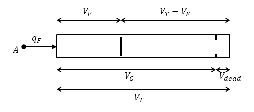
The diagram represents a gas-charged accumulator. The vertical separator divides the total accumulator volume, VT, into the fluid chamber on the left and the gas chamber on the right. The distance between the left side and the separator defines the fluid volume, VF. The distance between the right side and the separator defines the gas volume, VT – VF. The fluid chamber capacity, VC, is less than the total accumulator volume, VT, so that the gas volume never becomes zero.
The block models the hard stop contact pressure with a stiffness term and a damping term. The relationship of the gas pressure and gas volume between the current state and the precharge state is given by the polytropic relation, with pressure balanced at the separator
where:
| VT | Total volume of the accumulator, including the fluid chamber and the gas chamber |
| VF | Volume of fluid in the accumulator |
| Vinit | Initial volume of fluid in the accumulator |
| VC | Fluid chamber capacity, which is the difference between total accumulator volume and the gas chamber dead volume |
| Vdead | Gas chamber dead volume, which is a small portion of the gas chamber that remains filled with gas when the fluid chamber is at capacity |
| pF | Fluid pressure (gauge) in the fluid chamber, which is equal to the pressure at the accumulator inlet |
| ppr | Pressure (gauge) in the gas chamber when the fluid chamber is empty |
| pA | Atmospheric pressure |
| pG | Gas pressure (gauge) in the gas chamber |
| pHS | Hard-stop contact pressure |
| Ks | Hard-stop stiffness coefficient |
| Kd | Hard-stop damping coefficient |
| k | Specific heat ratio (adiabatic index) |
| qF | Fluid flow rate into the accumulator, which is positive if fluid flows into the accumulator |
The flow rate into the accumulator is the rate of change of the fluid volume:
At t = 0, the initial condition is VF = Vinit, where Vinit is the value you assign to the Initial fluid volume parameter.
Variables
To set the priority and initial target values for the block variables prior to simulation, use the Initial Targets section in the block dialog box or Property Inspector. For more information, see Set Priority and Initial Target for Block Variables.
Nominal values provide a way to specify the expected magnitude of a variable in a model. Using system scaling based on nominal values increases the simulation robustness. Nominal values can come from different sources, one of which is the Nominal Values section in the block dialog box or Property Inspector. For more information, see Modify Nominal Values for a Block Variable.
Assumptions and Limitations
The process in the gas chamber is assumed to be polytropic.
Loading on the separator, such as inertia or friction, is not considered.
Inlet hydraulic resistance is not considered.
Fluid compressibility is not considered.
Examples

Engine Cooling System
Model an engine cooling system with an oil cooling circuit.

House Heating System
Model a simple house heating system. The model contains a heater, a controller, and a house structure with four radiators and four rooms. Each room exchanges heat with the environment through its exterior walls, roof, and windows. Each path is simulated as a combination of a thermal convection, thermal conduction, and the thermal mass. It is assumed that heat is not transferred internally between rooms. The heater consists of a furnace, a boiler, an accumulator, and a pump to circulate hot water in the system. The controller starts admitting fuel into the furnace if the overall average temperature of rooms falls below 21 degree C and it stops if the temperature exceeds 25 degree C. The simulation calculates the heating cost and indoor temperatures.