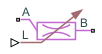
Main Content

Orifice (G)

Flow restriction in a gas network

  • Orifice (G) block

Libraries:
Simscape / Fluids / Gas / Valves & Orifices

Description

The Orifice (G) block represents the pressure loss incurred in a gas network due to a purely resistive element of fixed or variable size, such as a flow restriction, orifice, or valve. You can use orifices to measure and report gas flow characteristics.

Orifice Parameterizations

The block behavior depends on the Orifice parametrization parameter:

  • Cv flow coefficient — The flow coefficient Cv determines the block parameterization. The flow coefficient measures the ease with which a gas can flow when driven by a certain pressure differential.

  • Kv flow coefficient — The flow coefficient Kv, where Kv=0.865Cv, determines the block parameterization. The flow coefficient measures the ease with which a gas can flow when driven by a certain pressure differential.

  • Sonic conductance — The sonic conductance of the resistive element at steady state determines the block parameterization. The sonic conductance measures the ease with which a gas can flow when choked, which is a condition in which the flow velocity is at the local speed of sound. Choking occurs when the ratio between downstream and upstream pressures reaches a critical value known as the critical pressure ratio.

  • Orifice area — The size of the flow restriction determines the block parametrization.

Opening Characteristics

When you set Orifice type to Variable, the block uses the input at port L to control certain parameters. This input is the control signal and it is associated with stroke or lift percent. The control signal ranges in value from 0 to 1. If you specify a lesser or greater value, the block saturates the value to the nearest of the two limits.

The conversion from a control signal to the chosen measure of flow capacity depends on the Opening characteristic parameterization. Flow is maximally restricted when the control signal is 0 and minimally restricted when the control signal is 1. In between these values, the flow rate achieved within the resistive element depends on whether the opening parameterization is linear or based on tabulated data:

  • Linear — The measure of flow capacity is proportional to the control signal at port L. The two values vary in tandem until the control signal either drops below 0 or rises above 1. As the control signal rises from 0 to 1, the measure of flow capacity scales from the specified minimum to the specified maximum.

    When you set Orifice parameterization to Sonic conductance, the block treats the critical pressure ratio and subsonic index as constants that are independent of control signal. When you set Orifice parameterization to Cv flow coefficient or Kv flow coefficient, the block treats the parameter xT pressure differential ratio factor at choked flow as a constant independent of the control signal.

  • Tabulated — The block calculates the measure of flow capacity as a function of the control signal at port L. This function is based on a one-way lookup table. The tabulated data must be specified so the measure of flow capacity increases monotonically with the control signal.

    When you set Orifice parameterization to Sonic conductance, the block treats the critical pressure ratio as a function of the control signal and treats the subsonic index as a constant.. When you set Orifice parameterization to Cv flow coefficient or Kv flow coefficient, the block treats the parameter xT pressure differential ratio factor at choked flow as a function of the control signal.

Numerical Smoothing

When the Orifice type parameter is Variable, the Opening characteristic parameter is Linear, and the Smoothing factor parameter is nonzero, the block applies numerical smoothing to the control signal from port L. Enabling smoothing helps maintain numerical robustness in your simulation.

For more information, see Numerical Smoothing.

Momentum Balance

The block equations depend on the Orifice parametrization parameter. When you set Orifice parametrization to Cv flow coefficient parameterization, the mass flow rate, m˙, is

m˙=CvN6Y(pinpout)ρin,

where:

  • Cv is the flow coefficient.

  • N6 is a constant equal to 27.3 for mass flow rate in kg/hr, pressure in bar, and density in kg/m3.

  • Y is the expansion factor.

  • pin is the inlet pressure.

  • pout is the outlet pressure.

  • ρin is the inlet density.

The expansion factor is

Y=1pinpout3pinFγxT,

where:

  • Fγ is the ratio of the isentropic exponent to 1.4.

  • xT is the value of the xT pressure differential ratio factor at choked flow parameter.

The block smoothly transitions to a linearized form of the equation when the pressure ratio, pout/pin, rises above the value of the Laminar flow pressure ratio parameter, Blam,

m˙=CvN6Ylamρavgpavg(1Blam)(pinpout),

where:

Ylam=11Blam3FγxT.

When the pressure ratio, pout/pin, falls below 1FγxT, the orifice becomes choked and the block switches to the equation

m˙=23CvN6FγxTpinρin.

When you set Orifice parametrization to Kv flow coefficient parameterization, the block uses these same equations, but replaces Cv with Kv by using the relation Kv=0.865Cv. For more information on the mass flow equations when the Orifice parametrization parameter is Kv flow coefficient parameterization or Cv flow coefficient parameterization, see [2][3].

When you set Orifice parametrization to Sonic conductance parameterization, the mass flow rate, m˙, is

m˙=CρrefpinTrefTin[1(poutpinBcrit1Bcrit)2]m,

where:

  • C is the sonic conductance.

  • Bcrit is the critical pressure ratio.

  • m is the value of the Subsonic index parameter.

  • Tref is the value of the ISO reference temperature parameter.

  • ρref is the value of the ISO reference density parameter.

  • Tin is the inlet temperature.

The block smoothly transitions to a linearized form of the equation when the pressure ratio, pout/pin, rises above the value of the Laminar flow pressure ratio parameter Blam,

m˙=CρrefTrefTavg[1(BlamBcrit1Bcrit)2]m(pinpout1Blam).

When the pressure ratio, pout/pin, falls below the critical pressure ratio, Bcrit, the orifice becomes choked and the block switches to the equation

m˙=CρrefpinTrefTin.

For more information on the mass flow equations when the Orifice parametrization parameter is Sonic conductance parameterization, see [1].

When you set Orifice parametrization to Orifice area parameterization, the mass flow rate, m˙, is

m˙=CdSr2γγ1pinρin(poutpin)2γ[1(poutpin)γ1γ1(SRS)2(poutpin)2γ],

where:

  • Sr is the orifice or valve area.

  • S is the value of the Cross-sectional area at ports A and B parameter.

  • Cd is the value of the Discharge coefficient parameter.

  • γ is the isentropic exponent.

The block smoothly transitions to a linearized form of the equation when the pressure ratio, pout/pin, rises above the value of the Laminar flow pressure ratio parameter, Blam,

m˙=CdSr2γγ1pavg2γγρavgBlam2γ[1Blamγ1γ1(SRS)2Blam2γ](pinγ1γpoutγ1γ1Blamγ1γ).

When the pressure ratio, pout/pin, falls below(2γ+1)γγ1 , the orifice becomes choked and the block switches to the equation

m˙=CdSR2γγ+1pinρin1(γ+12)2γ1(SRS)2.

For more information on the mass flow equations when the Orifice parametrization parameter is Orifice area parameterization, see [4].

Mass Balance

The block assumes the volume and mass of fluid inside the resistive element is very small and ignores these values. As a result, no amount of fluid can accumulate in the resistive element. By the principle of conservation of mass, the mass flow rate into the valve through one port equals that out of the valve through the other port

m˙A+m˙B=0,

where m˙ is defined as the mass flow rate into the valve through the port indicated by the A or B subscript.

Energy Balance

The resistive element of the block is an adiabatic component. No heat exchange can occur between the fluid and the wall that surrounds it. No work is done on or by the fluid as it traverses from inlet to outlet. Energy can flow only by advection, through ports A and B. By the principle of conservation of energy, the sum of the port energy flows is always equal to zero

ϕA+ϕB=0,

where ϕ is the energy flow rate into the valve through ports A or B.

Assumptions and Limitations

  • The Sonic conductance setting of the Orifice parameterization parameter is for pneumatic applications. If you use this setting for gases other than air, you may need to scale the sonic conductance by the square root of the specific gravity.

  • The equation for the Orifice area parameterization is less accurate for gases that are far from ideal.

  • This block does not model supersonic flow.

Ports

Input

expand all

Control signal that specifies the opening of the orifice. In some valves, this represents the stroke or lift percent. The orifice is fully closed at a value of 0 and fully open at a value of 1.

Dependencies

To enable this parameter, set Orifice type to Variable.

Conserving

expand all

Gas conserving port associated with the opening through which the flow enters or exits the flow resistance. The block has no intrinsic directionality. The port can serve as the inlet or outlet, depending on the direction of the flow.

Gas conserving port associated with the opening through which the flow enters or exits the flow resistance. The block has no intrinsic directionality. The port can serve as the inlet or outlet, depending on the direction of the flow.

Parameters

expand all

Type of orifice defined by the orifice area. When you set this parameter to Variable, the orifice area varies according to the input signal received at port L.

Method to calculate the mass flow rate.

  • Cv flow coefficient — The flow coefficient Cv determines the block parameterization.

  • Kv flow coefficient — The flow coefficient Kv, where Kv=0.865Cv, determines the block parameterization.

  • Sonic conductance — The sonic conductance of the resistive element at steady state determines the block parameterization.

  • Orifice area — The size of the flow restriction determines the block parametrization.

Method by which to convert the control signal specified at port L to the chosen measure of flow capacity.

Dependencies

To enable this parameter, set Orifice type to Variable.

Vector of control signal values at which to specify the chosen measure of flow capacity: Sonic conductance vector, Cv coefficient vector, Kv coefficient vector, or Orifice area vector. The control signal is between 0 and 1, with each value corresponding to an opening fraction of the resistive element. The greater the value, the greater the opening and easier the flow.

The opening fractions must increase monotonically across the vector from left to right. The size of this vector must be the same as the Sonic conductance vector, Cv coefficient vector, Kv coefficient vector, or Orifice area vector parameter.

Dependencies

To enable this parameter, set Orifice type to Variable, and Opening characteristic to Tabulated.

Value of the Cv flow coefficient when the control signal specified at port L is 1 and restriction area available for flow is at a maximum. This parameter measures the ease with which the gas traverses the resistive element when driven by a pressure differential.

Dependencies

To enable this parameter, set Orifice type to Variable, Orifice parameterization to Cv flow coefficient, and Opening characteristic to Linear.

Ratio between the inlet pressure, pin, and the outlet pressure, pout, defined as (pinpout)/pin where choking first occurs. If you do not have this value, look it up in table 2 in ISA-75.01.01 [3]. Otherwise, the default value of 0.7 is reasonable for many valves.

Dependencies

To enable this parameter, set Orifice parameterization to Cv flow coefficient or Kv flow coefficient.

Ratio of the flow rate of the orifice when it is closed to when it is open.

Dependencies

To enable this parameter, set Orifice type to Variable, and Opening characteristic to Linear.

Continuous smoothing factor that introduces a layer of gradual change to the flow response when the orifice is in near-open or near-closed positions. Set this parameter to a nonzero value less than one to increase the stability of your simulation in these regimes.

Dependencies

To enable this parameter, set Orifice type to Variable, and Opening characteristic to Linear.

Vector of Cv flow coefficients. Each coefficient corresponds to a value in the Opening fraction vector parameter. This parameter measures the ease with which the gas traverses the resistive element when driven by a pressure differential. The flow coefficients must increase monotonically from left to right, with greater opening fractions representing greater flow coefficients. The size of the vector must be the same as the Opening fraction vector.

Dependencies

To enable this parameter, set Orifice type to Variable, Orifice parameterization to Cv flow coefficient, and Opening characteristic to Tabulated.

Value of the constant Cv flow coefficient. This parameter measures the ease with which the gas traverses the resistive element when driven by a pressure differential.

Dependencies

To enable this parameter, set Orifice type to Constant and Orifice parameterization to Cv flow coefficient.

Value of the Kv flow coefficient when the control signal specified at port L is 1 and the restriction area available for flow is at a maximum. This parameter measures the ease with which the gas traverses the resistive element when driven by a pressure differential.

Dependencies

To enable this parameter, set Orifice type to Variable, Orifice parameterization to Kv flow coefficient, and Opening characteristic to Linear.

Vector of Kv flow coefficients. Each coefficient corresponds to a value in the Opening fraction vector parameter. This parameter measures the ease with which the gas traverses the resistive element when driven by a pressure differential. The flow coefficients must increase monotonically from left to right, with greater opening fractions representing greater flow coefficients. The size of the vector must be the same as the Opening fraction vector parameter.

Dependencies

To enable this parameter, set Orifice type to Variable, Orifice parameterization to Kv flow coefficient, and Opening characteristic to Tabulated.

Value of the constant Kv flow coefficient. This parameter measures the ease with which the gas traverses the resistive element when driven by a pressure differential.

Dependencies

To enable this parameter, set Orifice type to Constant and Orifice parameterization to Kv flow coefficient.

Value of the sonic conductance when the control signal specified at port L is 1 and cross-sectional area available for flow is at a maximum.

Dependencies

To enable this parameter, set Orifice type to Variable, Orifice parameterization to Sonic conductance, and Opening characteristic to Linear.

Pressure ratio at which flow first begins to choke and the flow velocity reaches its maximum, given by the local speed of sound. The pressure ratio is the outlet pressure divided by inlet pressure.

Dependencies

To enable this parameter, set either:

  • Orifice type to Constant and Orifice parameterization to Sonic conductance.

  • Orifice type to Variable, Orifice parameterization to Sonic conductance, and Opening characteristic to Linear.

Empirical value used to more accurately calculate the mass flow rate in the subsonic flow regime.

Dependencies

To enable this parameter, set Orifice parameterization to Sonic conductance.

Temperature at standard reference atmosphere, defined as 293.15 K in ISO 8778.

You only need to adjust the ISO reference parameter values if you are using sonic conductance values that are obtained at difference reference values.

Dependencies

To enable this parameter, set Orifice parameterization to Sonic conductance.

Density at standard reference atmosphere, defined as 1.185 kg/m3 in ISO 8778.

You only need to adjust the ISO reference parameter values if you are using sonic conductance values that are obtained at difference reference values.

Dependencies

To enable this parameter, set Orifice parameterization to Sonic conductance.

Vector of sonic conductances inside the resistive element. Each conductance corresponds to a value in the Opening fraction vector parameter. The sonic conductances must increase monotonically from left to right, with greater opening fractions representing greater sonic conductances. The size of the vector must be the same as the Opening fraction vector parameter.

Dependencies

To enable this parameter, set Orifice type to Variable, Orifice parameterization to Sonic conductance, and Opening characteristic to Tabulated.

Vector of critical pressure ratios at which the flow first chokes, with each critical pressure ratio corresponding to a value in the Opening fraction vector parameter. The critical pressure ratio is the fraction of downstream-to-upstream pressures at which the flow velocity reaches the local speed of sound. The size of the vector must be the same as the Opening fraction vector parameter.

Dependencies

To enable this parameter, set Orifice type to Variable, Orifice parameterization to Sonic conductance, and Opening characteristic to Tabulated.

Ratio, measured at the onset of choking, of the mass flow rate through the resistive element to the product of the upstream pressure and mass density at standard conditions as defined in ISO 8778. This parameter determines the maximum flow rate allowed at a given upstream pressure.

Dependencies

To enable this parameter, set Orifice type to Constant and Orifice parameterization to Sonic conductance.

Cross-sectional area of the orifice opening when the control signal specified at port L is 1 and the cross-sectional area available for flow is at a maximum.

Dependencies

To enable this parameter, set Orifice type to Variable, Orifice parameterization to Orifice area, and Opening characteristic to Linear.

Correction factor that accounts for discharge losses in theoretical flows.

Dependencies

To enable this parameter, set Orifice parameterization to Orifice area.

Vector of cross-sectional areas of the orifice opening. The values in this vector correspond one-to-one with the elements in the Opening fraction vector parameter. The first element of this vector is the orifice leakage area and the last element is the maximum orifice area.

Dependencies

To enable this parameter, set Orifice type to Variable, Orifice parameterization to Orifice area, and Opening characteristic to Tabulated.

Cross-sectional area of the orifice opening.

Dependencies

To enable this parameter, set Orifice type to Constant and Orifice parameterization to Orifice area.

Pressure ratio at which flow transitions between laminar and turbulent flow regimes. The pressure ratio is the outlet pressure divided by inlet pressure. Typical values range from 0.995 to 0.999.

Area normal to the flow path at each port. The ports are equal in size. The value of this parameter should match the inlet area of the components to which the resistive element connects.

References

[1] ISO 6358-3. "Pneumatic fluid power – Determination of flow-rate characteristics of components using compressible fluids – Part 3: Method for calculating steady-state flow rate characteristics of systems". 2014.

[2] IEC 60534-2-3. "Industrial-process control valves – Part 2-3: Flow capacity – Test procedures". 2015.

[3] ANSI/ISA-75.01.01. "Industrial-Process Control Valves – Part 2-1: Flow capacity – Sizing equations for fluid flow underinstalled conditions". 2012.

[4] P. Beater. Pneumatic Drives. Springer-Verlag Berlin Heidelberg. 2007.

Extended Capabilities

C/C++ Code Generation
Generate C and C++ code using Simulink® Coder™.

Version History

Introduced in R2018a

expand all