Porting Plate Variable Orifice
(To be removed) Variable orifice between piston and porting plate
The Hydraulics (Isothermal) library will be removed in a future release. Use the Isothermal Liquid library instead.
For more information on updating your models, see Upgrading Hydraulic Models to Use Isothermal Liquid Blocks.
Library
Pumps and Motors

Description
Porting plate is a key element of axial-piston machines. Its objective is to provide communication between pistons and pump ports during the rotor, or cylinder block, rotation. The porting plate is equipped with two crescent-shaped slots, one of which is connected to the intake port while the other is channeled to the discharge port. The pistons are carried along the porting plate slots, thus periodically connecting the piston to either the intake or the discharge port of the machine.
The preceding diagram shows an axial-piston machine with five pistons, where:
Porting plate
Rotor
Piston
Driving shaft
Swash plate
During rotor rotation, every piston gets connected to one of the porting slots. These piston connections, modeled as variable orifices, are reflected in the schematic model of a piston, shown in the following illustration.
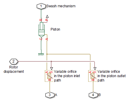
The Porting Plate Variable Orifice block is a model of a variable orifice created between the piston chamber and a slot on a porting plate. Two Porting Plate Variable Orifice blocks are necessary in the model of a piston, to simulate connection to the intake and the discharge port, respectively.
The calculation diagram of the porting plate variable orifice is shown in the next illustration.
The model assumes that the slot is shifted by a pressure carryover angle ψ from the reference point in the direction of orifice rotation. Generally, r / R ≤ ψ ≤ 3·r / R , where r is the orifice radius and R is the piston pitch radius. A small triangular-shaped transition slot is placed at the beginning of the major slot, to avoid sudden pressure change. To avoid direct connection between the intake and discharge slots, the transition slot angle θ must be less than ψ – r / R . The transition slot area is assumed to be linearly dependent on the rotation angle and characterized by its maximum area. There are six distinctive angles defining the relationship between the rotation angle γ and the orifice opening, as listed in the following table.
| No | Nomenclature | Value | Description |
|---|---|---|---|
| 1 | γ1 | ψ – θ – r / R | Opening of transition slot starts. |
| 2 | γ2 | ψ – r / R | Opening of the major slot starts. The orifice contacts with the transition slot. |
| 3 | γ3 | ψ + r / R | Major slot full opening starts. |
| 4 | γ4 | ψ + r / R + 0.01 | Transition slot ends. |
| 5 | γ5 | π – 2· r / R | Major slot full opening ends. |
| 6 | γ6 | π | Major slot opening ends. |
The variable orifice is fully opened in the α0 region
ψ + r / R ≤ γ ≤ π – 2· r / R
where γ is the rotation angle.
The orifice area is computed with the following equations:
where
| A | Orifice area |
| Atr | Transition slot maximum area |
| Aleak | Closed orifice leakage area |
After the area has been determined, the flow rate through the orifice is computed with the following equations:
where
| q | Flow rate |
| p | Pressure differential |
| pA, pB | Gauge pressures at the block terminals |
| CD | Flow discharge coefficient |
| DH | Orifice hydraulic diameter |
| ρ | Fluid density |
| ν | Fluid kinematic viscosity |
| pcr | Minimum pressure for turbulent flow |
| Recr | Critical Reynolds number |
The Porting Plate Variable Orifice block model is essentially a building block intended for use in various piston machines. The model accounts for the flow regime by computing the Reynolds number and comparing it with its critical value. No inertial effects are considered in the model.
Connections A and B are hydraulic conserving ports associated with the inlet and outlet of the orifice. Connection G is a physical signal port associated with the input signal for the cylinder block angle. The input signal at port G is treated as an angle, in radians, therefore it is essential that the input signal representing angular displacement is kept within the range from 0 to 2π. Connect port G to the output port of an Angle Sensor block to meet this requirement.
The flow rate is considered positive if it flows from A to B. At initial position, the orifice is assumed to be shifted by the pressure carryover angle from the slot. When the block rotates in the positive direction, the orifice starts opening. To adjust the initial position of the orifice with respect to the slot, use the Phase angle parameter.
Basic Assumptions and Limitations
The model accounts for the viscous friction in the piston-plate contact.
No inertial effects are considered.
The plate angular displacements are considered to be small.
The joint between the piston and the plate permanently maintains contact between the piston and the plate.
Parameters
- Piston pitch radius
The radius of the pitch circle where the pistons are located. The parameter must be greater than zero. The default value is
0.05m.- Orifice diameter
The diameter of the orifice at the bottom of the piston chamber. The parameter must be greater than zero. The default value is
0.005 m.- Pressure carryover angle
The angle introduced between to slot and the orifice to avoid abrupt pressure change and decrease leakage. This angle is marked ψ in the preceding calculation diagram. The angle is expected to be in the range r / R ≤ ψ ≤ 3·r / R , where r is the orifice radius and R is the piston pitch radius. The default value is
0.06rad.- Phase angle
This parameter sets the orifice initial angular position with respect to the slot. The default value is
0, which means that the orifice is shifted by the pressure carryover angle from the slot.- Transition slot angle
The angle covered by a small, triangular-shaped transition slot placed before the major slot to avoid sudden pressure change, as shown in the preceding calculation diagram. To avoid direct connection between the intake and discharge slots, the transition slot angle θ must be less than ψ – r / R . The default value is
0.01rad.- Transition slot maximum area
The maximum cross-sectional area of the transition slot. The slot area is assumed to be linearly-dependent on the rotation angle and reaches its maximum when the orifice approaches the major slot. The default value is
1e-6m.- Flow discharge coefficient
Semi-empirical parameter for orifice capacity characterization. Its value depends on the geometrical properties of the orifice, and usually is provided in textbooks or manufacturer data sheets. The default value is
0.6.- Critical Reynolds number
The maximum Reynolds number for laminar flow. The transition from laminar to turbulent regime is assumed to take place when the Reynolds number reaches this value. The value of the parameter depends on the orifice geometrical profile. You can find recommendations on the parameter value in hydraulics textbooks. The default value is
12, which corresponds to a round orifice in thin material with sharp edges.- Leakage area
The total area of possible leaks in the completely closed orifice. The main purpose of the parameter is to maintain numerical integrity of the circuit by preventing a portion of the system from getting isolated after the valve is completely closed. The parameter value must be greater than 0. The default value is
1e-9m^2.
Global Parameters
Parameters determined by the type of working fluid:
Fluid density
Fluid kinematic viscosity
Use the Hydraulic Fluid block or the Custom Hydraulic Fluid block to specify the fluid properties.
Ports
The block has the following ports:
AHydraulic conserving port associated with the orifice inlet.
BHydraulic conserving port associated with the orifice outlet.
GPhysical signal input port that conveys the angular position of the orifice to the block. The signal applied to the port is treated as an angle, in radians, and must be in the range between 0 and 2π.
Examples
The Hydraulic Axial-Piston Pump with Load-Sensing and Pressure-Limiting Control example models a test rig designed to investigate interaction between an axial-piston pump and a typical control unit, simultaneously performing the load-sensing and pressure-limiting functions. To assure required accuracy, the model of the pump must account for such features as interaction between pistons, swash plate, and porting plate, which makes it necessary to build a detailed pump model.