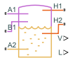
Tank (G-TL)
Pressurized tank with variable gas and thermal liquid volumes
Libraries:
Simscape /
Fluids /
Thermal Liquid /
Tanks & Accumulators
Description
The Tank (G-TL) block models the accumulation of mass and energy in a chamber with separate gas and thermal liquid volumes. The total fluid volume is fixed, but the individual gas and thermal liquid volumes can vary. Two gas ports allow for gas flow and a variable number of thermal liquid ports, ranging from one to six, allow for thermal liquid flow. The thermal liquid ports can be at different elevations.
The tank is pressurized, but the pressurization is not fixed. It changes during simulation with the pressure in the gas volume. The pressure rises when the pressure of the gas volume rises and falls when the pressure of the gas volume falls. The thermal liquid volume is assumed to be at equilibrium with the gas volume and its pressure is therefore the same as that of the gas.
The fluid volumes can exchange energy with other fluid components and with the environment but not with each other. The fluid volumes behave as if they were isolated from each other by an insulated membrane. Energy exchanges with other components occur through gas or thermal liquid ports, while exchanges with the environment occur, strictly in the form of heat, through thermal ports.
Use this block to model components such as drain tanks, in which water condensed from a compressed gas system is trapped at the bottom by gravity and expelled through a drain outlet. Note, however, that neither gas nor thermal liquid domains capture the effects of phase change—and therefore that this block cannot capture the effects of condensation.
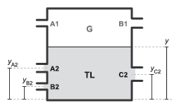
Thermal Liquid Ports
You can specify the number of thermal liquid ports using the Number of inlets parameter:
| Number of inlets | Exposed thermal liquid ports |
|---|---|
1 | Port A2 |
2 | Ports A2 and B2 |
3 | Ports A2, B2, and C2 |
4 | Ports A2, B2, C2, and D2 |
5 | Ports A2, B2, C2, D2, and E2 |
6 | Ports A2, B2, C2, D2, E2, and F2 |
Fluid Volumes
The total volume of the tank is equal to the sum of the gas and thermal liquid volumes that it contains,
where V is the volume and T, L, and G stand for total, liquid, and gas. Because the total volume is fixed, the time rate of change of the gas volume must be the reverse of that measured for the thermal liquid volume,
The time rate of change of the thermal liquid volume is calculated by differentiating the expression
where M is mass and ρ is density. The differentiation gives the mass flow rate into the thermal liquid volume,
The time rate of change of the thermal liquid density is
where:
β is the thermal bulk modulus.
ɑ is the isobaric thermal expansion coefficient.
p is the fluid pressure.
T is the fluid temperature.
Rearranging terms gives the rate of change of the thermal liquid volume and, by extension, of the gas volume
Mass Balance
The rate of mass accumulation in each fluid volume is equal to the net mass flow rate into that fluid volume. In the thermal liquid volume
ML is the rate of mass accumulation in the thermal liquid volume and are the individual mass flow rates into that volume through the thermal liquid ports A2, B2, C2, D2, E2, or F2. The rate of mass accumulation contains contributions from pressure, temperature, and volume change,
where the pressure of the thermal liquid volume is by definition equal to the pressure of the gas volume and the equation is therefore written in terms of the gas pressure. In the gas volume
where MG is the rate of mass accumulation in the gas volume and are the individual mass flow rates into that volume through the gas ports A1 and B1. As with the thermal liquid volume, the rate of mass accumulation contains contributions from pressure, temperature, and volume change
where the pressure and temperature derivatives depend on the type of gas specified in the Gas Properties (G) block. The equations section of the Translational Mechanical Converter (G) page defines the derivatives. Replacing VG with the expression previously obtained for this variable and combining the two expressions for MG
Rearranging terms gives the final expression for the mass balance in the gas volume
where has been replaced with the summation of the mass flow rates into the thermal liquid volume.
Energy Balance
The rate of energy accumulation in each fluid volume is the sum of the energy flow rates through the fluid inlets, the heat flow rate through the corresponding thermal port, and the energy flow rate due to volume changes. For the gas volume
where:
U is the total energy of the fluid volume.
h is the fluid enthalpy.
Q is the heat flow rate through the thermal port.
ϕi are the energy flow rates through the fluid inlets.
As before, the pressure and temperature derivatives depend on the type of gas specified in the Gas Properties (G) block. See the equations section of the Translational Mechanical Converter (G) page for the definitions. For the thermal liquid volume
where the pressure derivative is
and the temperature derivative is
where cp is the isobaric specific heat of the thermal liquid inside the tank.
Momentum Balance
Flow resistance due to friction or other causes is ignored in both fluid volumes. The block also ignores the effect of elevation on inlet pressure, but only on the gas side. The gas inlet pressures are therefore equal to each other and to the internal pressure of the gas volume
The thermal liquid inlet pressures are each a function of inlet depth. The internal pressure of the thermal liquid volume is equal to the gas volume, pL = pG. The block includes dynamic pressures, pi,dyn, at the inlets by using the equation
where y is the elevation of the thermal liquid surface, yi is the elevation of the thermal liquid inlet, and g is the gravitational constant. The term y - yi gives the depth of the thermal liquid inlet with respect to the gas-thermal liquid boundary. The dynamic pressure at each thermal liquid inlet depends on the direction of flow at that inlet
where vi is the flow velocity.
Variables
To set the priority and initial target values for the block variables prior to simulation, use the Initial Targets section in the block dialog box or Property Inspector. For more information, see Set Priority and Initial Target for Block Variables and Initial Conditions for Blocks with Finite Gas Volume.
Nominal values provide a way to specify the expected magnitude of a variable in a model. Using system scaling based on nominal values increases the simulation robustness. Nominal values can come from different sources, one of which is the Nominal Values section in the block dialog box or Property Inspector. For more information, see Modify Nominal Values for a Block Variable.
Assumptions and Limitations
Fluid momentum is lost at the tank inlet due to the sudden expansion into the tank volume.
Examples

Electric Vehicle Thermal Management
Model the thermal management system of a battery electric vehicle.
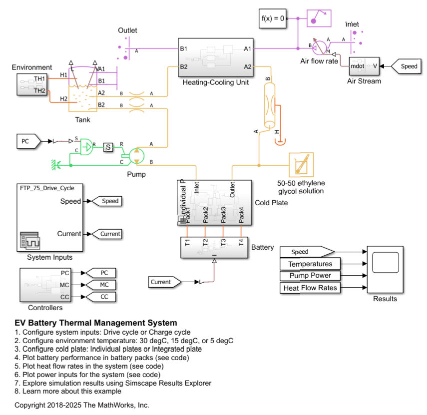
EV Battery Thermal Management System
An Electric Vehicle (EV) battery heating-cooling system. Maintaining the battery temperature within an optimal range is important for efficient charging and discharging. The model simulates either the FTP-75 drive cycle or a fast charge cycle at different environment temperatures. A thermal liquid coolant circuit conveys heat between the battery and the heating-cooling unit. For more information on designing EV battery cooling systems, see EV Battery Cooling System Design.